7. MYO-Joint
7.1. Type 1: Symmetric Hinge
This joint type provides 1 DoF of rotation along an axis parallel to the joint end planes. The provided angular range of rotation is symmetric with respect to the axis perpendicular to its interface plane provided by the structural bond. This DoF is provided by a combination of axle and rotational bearings. The basic structure of the joint is illustrated in Fig. 7.1.
Both joint ends are shaped as forks (the upper- and under joint forks) and provide an interface for the structural bond. The electrical interfaces on both joint ends are embedded in the structural bonds and the space between the upper and under fork is used for the electrical cabling. The attachment and guidance for the cable transmission are placed centrally for a symmetrical application of the force on the bearings.
Fig. 7.1 Illustration of the joint construction for Type 1
7.1.1. Variety 1
This implementation uses two axles placed on each side of the joint, supported by ball bearings to reduce the friction and increase the efficiency of the joint. Between the two axles, a disk-like structure is used to guide the cable while insuring a constant lever arm with respect to the joint rotation axis. The absolute position of the joint is measured using a Hall-effect sensor, comprising a magnet embedded in one of the axles and an electronic board located inside the joint. The corresponding sensor interface module (SIM) is located on the outside of the joint to be easily accessible for configuration purpose.
7.1.1.1. Illustrations
Dimensions
H Distance between joint end planes
W Maximal width of the joint
T Maximal thickness of the joint
X Height of the tilt axis
Θ Motion range of the joint
Implemented instances
Reference |
JOINT-SC2-T1-V1 |
||
|---|---|---|---|
Corresponding DP-Class |
II |
||
Dimensions |
H |
60 |
[mm] |
W |
55 |
[mm] |
|
T |
36 |
[mm] |
|
X |
29 |
[mm] |
|
Θ |
140 |
[°] |
|
M |
70 |
[g] |
|
Features
Under joint fork:
Both bearings are implemented in the under joint fork.
Two mechanical stoppers limit the motion range of the joint.
The structural bond (SB) is integrated on the under joint fork.
The topology of the force transmitting volume from the SB to the joint axis is optimised.
A holding device allows attaching a SIM-board on the side.
Upper joint fork:
Two cable attachments (CA-SC2-T2), allowing the bidirectional actuation of the joint, and a continuous guide for the cables are implemented.
The SB is integrated on the upper joint fork.
The topology of the force transmitting volume from the SB to the joint axis is optimised.
The “neck” of the upper joint fork features a location to add an extension, providing if necessary additional CA on the joint.
Both shafts of the joint are implemented with interference fit.
Sensor and electrical interfaces:
The sensor board and its protection cap can be easily fixed on the under joint fork.
To measure the movement between the joint parts, the magnet element of the sensor is mounted in the shaft.
The electrical interfaces are small PCBs which are embedded in the structural bonds.
Openings and cable channels are implemented to enable the electrical cabling between sensor and SIM-board and between the electrical interfaces of the structural bonds on both sides of the joint.
Material and fabrication
Element name |
Material |
Fabrication processes |
|---|---|---|
Upper hinge part Lower hinge part Sensor cap |
Polyamide (PA) |
|
Shaft |
Aluminium |
|
Bearing |
Steel |
|
7.1.1.2. Assembly Procedure
Material needed:
1 x Upper hinge part
1 x Lower hinge part
1 x Sensor cap
2 Bearings 625 5x16x5 mm
1 x shaft left side
1 x shaft sensor side
4 data wires 0,25 mm2
2 power wires highly flexible silicon 1,5 mm2
2 x connector boards, four spring contacts
8 x M1,6 x 6
7.1.1.3. Step 1: Mount sensor board
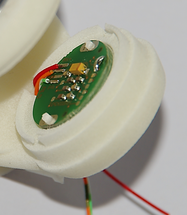
Push the sensor cables through the cable channel. Place the sensor board on the pins and glue on two points.
Tips:
for pre fixation of the board melt the plastic pins with a soldering iron
7.1.1.4. Step 2: Glue sensor cap
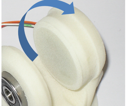
Put glue on the sensor cap and screw it on the housing.
Tips:
just a small amount of glue is needed
7.1.1.5. Step 3: Mount Ball Bearings
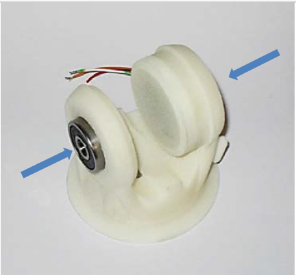
Put the ball bearings in the housing on both sides.
7.1.1.6. Step 4: Assemble upper and under hinge part
Assemble the upper and under hinge part.
Plug in the shafts to fix the joint parts.
Tips:
The shaft with magnet must on the sensor side
For better fixation put lock tide on the shafts
7.1.1.7. Step 5: Connect cables to the board
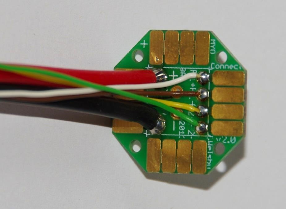
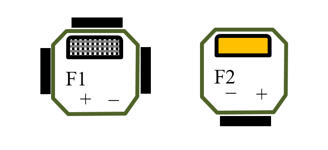
Prepare cable tree on connector boards.
Cut on 15 cm length:
4 data wires 0,25 mm2
2 power wires highly flexible silicon 1,5 mm2
Connector side:
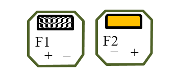
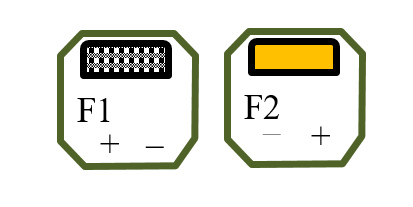
Pin colour code:
F1+ white
F1 - brown
F2 + yellow
F2 - green
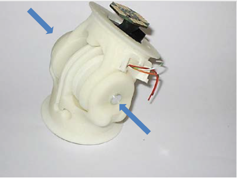
7.1.1.8. Step 6: Cabling
Place PCB carrier in SB.
Carrier orientation:
Push cable tree through the joint.
7.1.1.9. Step 7: Connect cables to the second board
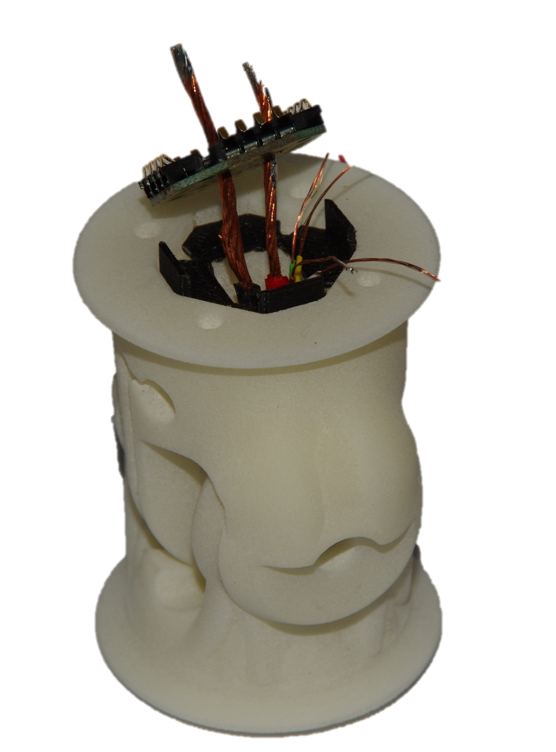
Skinning all cables long till the SB-pocket.
Pull cables through connector board and solder from top. Screw both connector boards to joint with four M1,6 screws.
Connector side:
Pin colour code:
F1+ white
F1 - brown
F2 + yellow
F2 - green
Tips:
Turn Joint in the position of the longest cable path!
Avoid cable crossovers by connecting to board
7.2. Type 2: Asymmetric Hinge
This joint type provides 1 DoF of rotation along an axis parallel to the joint end planes. In contrast to the symmetric hinge, the provided angular range of rotation is asymmetric with respect to the axis perpendicular to its interface plane provided by the structural bond. Following Principle II, this DoF is provided by a combination of axle and rotational bearings. The basic structure of the joint is illustrated in Fig. 7.1.
Both joint ends are shaped as forks (the upper- and under joint forks) and provide an interface for the structural bond. The electrical interfaces on both joint ends are embedded in the structural bonds and the space between the upper and under fork is used for the electrical cabling. The attachment and guidance for the cable transmission are placed centrally for a symmetrical application of the force on the bearings.
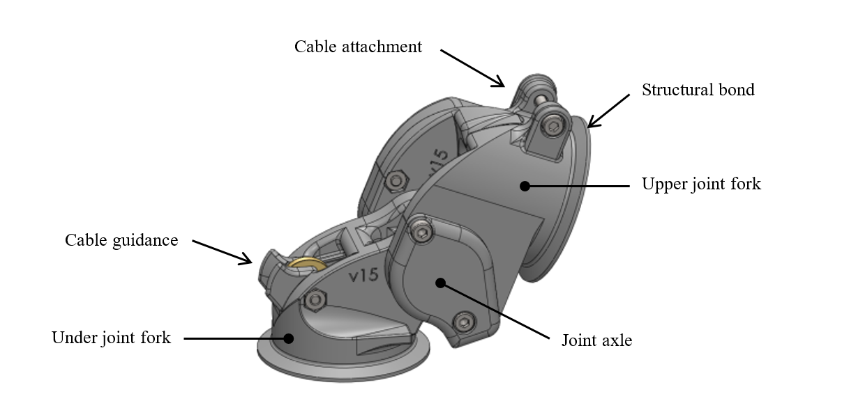
Fig. 7.2 Illustration of the joint construction
7.2.1. Variety 1 [obsolete]
This implementation uses a joint axle to the under joint fork and supported on each side by ball bearings mounted on the upper joint fork and secured with side covers. The absolute position of the joint is measured using a Hall-effect sensor, comprising a magnet embedded in the joint axle and an electronic board located on the side of the joint, together with its corresponding sensor interface module (SIM). The electronic boards are integrated in one of the side covers.
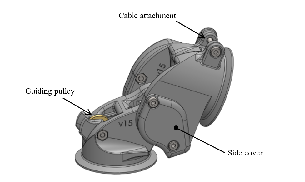
Fig. 7.3 Illustration of the joint construction
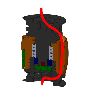
Given the constraint of asymmetric angular range, it was not possible to use the same mechanism for cable guidance as for the symmetric hinge joint, while preserving a compact joint design. Instead, the cable of the extension muscle is redirected by a guiding pulley (located on the under joint fork) towards the cable attachment (located on the upper joint fork) implemented using a pin mounted transversally to the cable direction.
This cable guidance implementation does not insure a constant lever arm length, which significantly decreases as the joint flexes, as shown in Fig. 7.4. Tests performed by ETH showed that this pronounced decrease of the lever arm length was prejudicial in applications. For that reason another asymmetric hinge variety was developed, which is described in the next section.
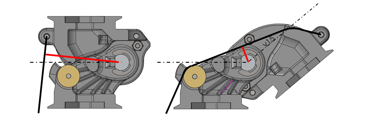
Fig. 7.4 Lever arm length variation of the extensor muscle cable (red line) as the asymmetric hinge joint (variety 1) flexes from 0° to 140°
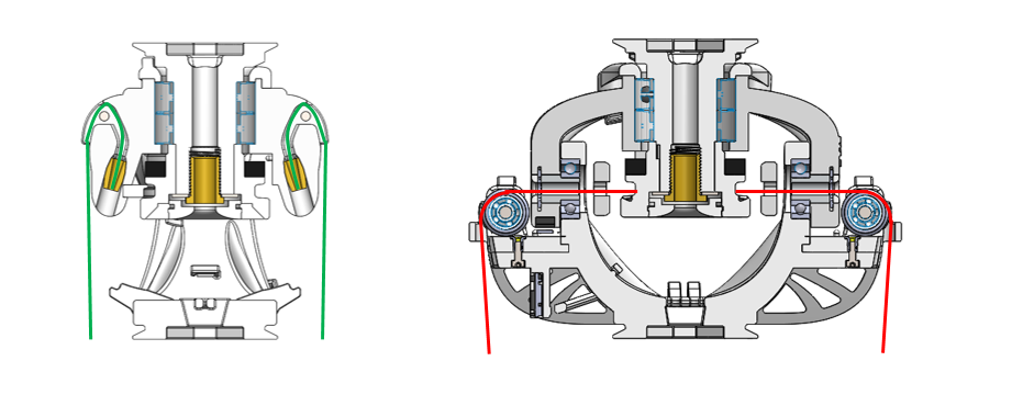
7.2.2. Variety 2
This variety has the same basic construction as variety 1 regarding the joint axle and bearing, as well as the implementation and location of the absolute position sensing.
The main difference with variety 1 lies in the implementation of the cable guidance. The guiding pulley and the cable attachment are both mounted on two metal sheets attached to the sides of the under and upper joint forks respectively. This construction has two benefits: (1) the decrease of the lever arm length as the joint flexes can be significantly reduced and (2) the lever arm length can be easily adjusted by exchanging the metal sheets. On the other hand, this configuration increases the risk that the cable jumps out of the guiding pulley. To prevent this, two mechanisms were devised to centre the cable attachment (cable centring mechanism) and to keep the cable running on the pulley (cable catching mechanisms).
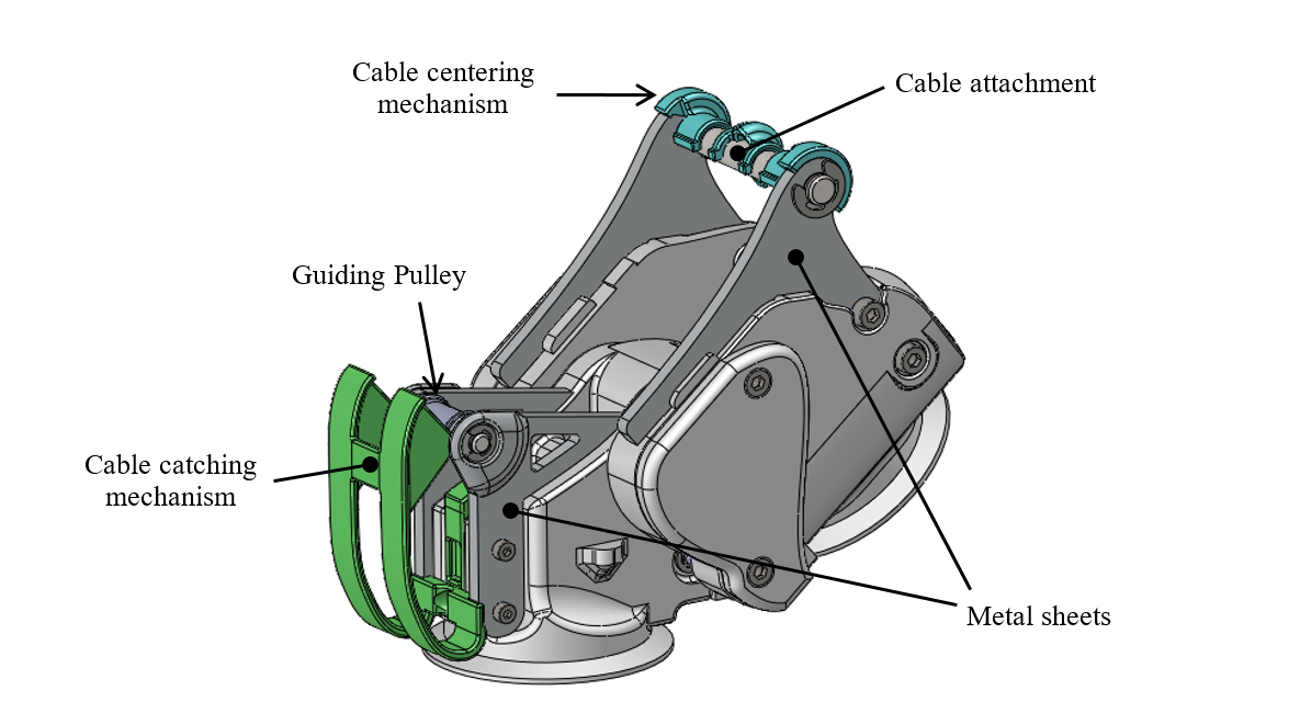
Fig. 7.5 Illustration of the joint construction
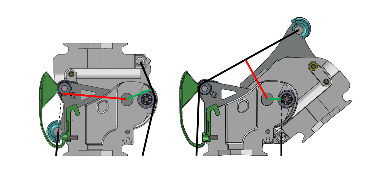
Fig. 7.6 Lever arm length variation of the extensor and flexor muscles cables (resp. red and green lines) as the asymmetric hinge joint (variety 2) flexes from 0° to 140°
7.2.2.1. Illustrations
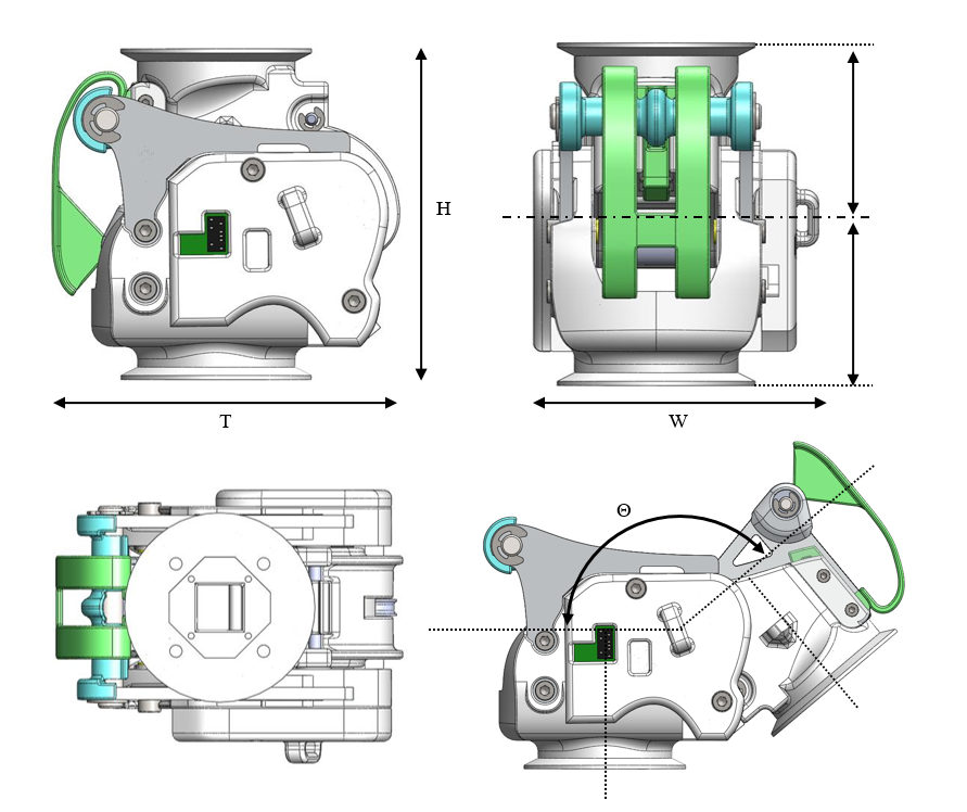
Dimensions
H Distance between joint end planes
W Maximal width of the joint
T Maximal thickness of the joint
X Height of the rotation axis
Θ Angular range of the joint
Implemented instances
Reference |
JOINT-SC2-T2-V2 |
||
|---|---|---|---|
Corresponding DP-Class |
II |
||
Dimensions |
H |
80 |
[mm] |
W |
66,25 |
[mm] |
|
T |
84 |
[mm] |
|
X |
40 |
[mm] |
|
Θ |
140 |
[°] |
|
M |
224 |
[g] |
|
Features
Under joint fork:
The joint axle is pressed through the under joint fork, while relative rotation is prevented via a chamfer.
The axle is axially secured with one circlip on each of its sides.
Two mechanical stoppers on each side of the under joint fork limit the extension of the joint.
The structural bond (SB) is integrated on the under joint fork.
M2 brass inserts are embedded in the under joint fork as fixation points for the metal sheets holding the guiding pulley.
A M2 brass insert is embedded in the top part of the under joint fork as fixation point for the cable catching mechanism.
Upper joint fork:
The ball bearings are mounted in the upper joint fork.
The bearings are axially secured on the medial side by the upper joint fork itself and on the lateral side by the two side covers screwed on the upper joint fork.
Two mechanical stoppers on each side of the upper joint fork limit the flexion of the joint.
The SB is integrated on the under joint fork.
M2 brass inserts are embedded in the upper joint fork as fixation points for the metal sheets holding the cable attachment for the extensor muscle cable.
Flexor muscle cable guidance and attachment:
The cable attachment is implemented as a transversal parallel pin around which the end of the cable is attached. The pin is pressed in the upper joint fork.
A pulley equipped with ball bearing is fixed on the under joint fork to guide the cable when the joint is close to most extended position.
Extensor muscle cable guidance and attachment:
The cable attachment is implemented as a transversal parallel pin around which the end of the cable is attached. The pin is supported by the two metal sheets inserted in the upper joint fork structure and additionally fixed to it with four screws.
To prevent that the cable slides laterally, a part (“cable centring clip”) is clipped on the pin to constraint the position of the cable to its centre.
The cable guidance is implemented as a roller born by a transversal parallel pin supported by the two metal sheets screwed to the under joint fork.
A part (“cable catching mechanism”) is fixed to top part of the under joint fork to prevent the cable to jump out of the roller when the joint extends while there is no tension in the cable. This part is shaped so as to deform in order to let the cable attachment pin pass under it and close afterwards when the joint extends or closes.
Sensor and electrical interfaces:
A magnet is glued to the joint axle.
The rotation of the magnet is measured by a Hall-effect sensor implemented in an IC mounted on the sensor board.
The signal provided by the sensor board is conditioned and transmitted by the SIM-board. Both boards are housed in one of the side covers.
Openings and cable channels are implemented to enable the electrical cabling between sensor and SIM-board and between the electrical interfaces of the structural bonds on both sides of the joint.
Material and fabrication
Element name |
Material |
Fabrication processes |
|---|---|---|
Upper joint fork Under joint fork Side covers Guiding pulleys Cable centering clip Cable catching mechanism |
Polyamide (PA) |
laser sintering |
Shaft |
Aluminium |
machining |
Bearings |
Steel |
purchase (standard component) |
Metal sheets |
Aluminium |
water jet cutting |
Parallel pins (cable attachment and pulley axles) |
Steel |
purchase (standard component) |
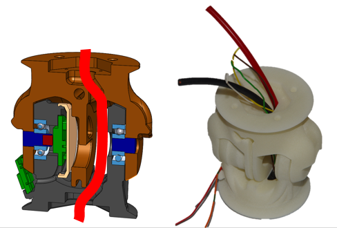
7.3. Type 3 – Pivot
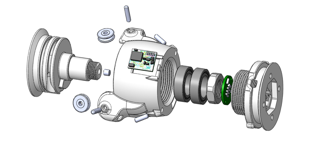
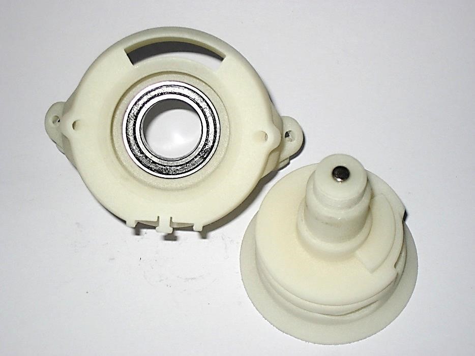
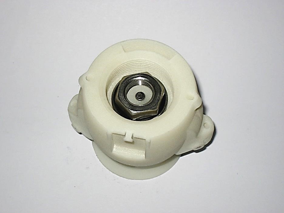
This joint type provides 1 DoF of rotation along an axis perpendicular to the joint end planes. Following Principle II, this DoF is provided by a combination of axle and rotational bearings. The basic structure of the joint is illustrated in Fig. 7.7. One side of the joint includes the joint axle and is called the pivot shaft. This part includes the cable attachments. The other side of the joint carries one or multiple bearings and is made of a barrel-shaped housing and a lid. The pivot shaft and the lid have each an interface for a structural bond. The electrical interfaces on both joint ends are embedded in the structural bonds and the electric cabling joining them is guided through the joint.
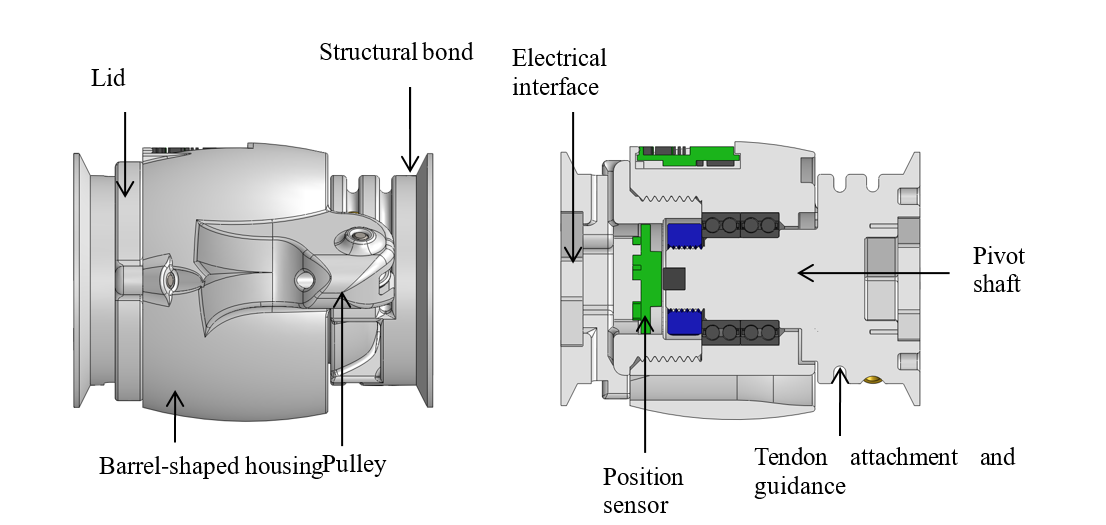
Fig. 7.7 Illustration of the joint construction for Type 2
7.3.1. Variety 1
This implementation provides a large symmetrical range of rotation of the joint. To reduce the friction and increase the efficiency of the joint, two ball bearings are used to support the joint axle.
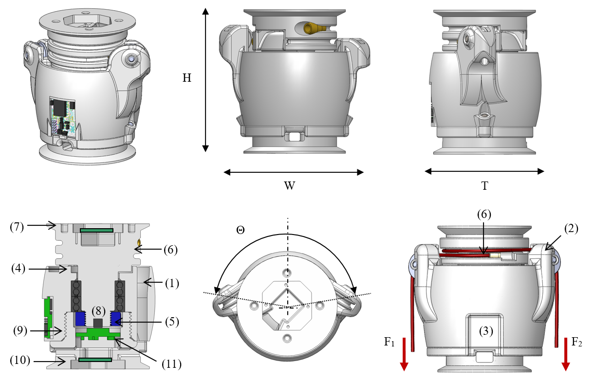
Dimensions
H Distance between joint end planes
W Maximal width of the joint
T Maximal thickness of the joint
Θ Motion range of the joint
Implemented instances
Reference |
JOINT-SC2-T3-V1 |
||
|---|---|---|---|
Corresponding DP-Class |
II |
||
Dimensions |
H |
65 |
[mm] |
W |
66,8 |
[mm] |
|
T |
50 |
[mm] |
|
Θ |
164 |
[°] |
|
M |
115 |
[g] |
|
Features
Barrel-shaped housing:
The barrel-shaped housing contains a reservoir for the electrical cables, into which the electric cable can freely move when the joint is rotating.
On the outside of the housing, two holding devices are embedded for the pulleys redirecting the cable transmission.
A holding bay in the housing allows attaching a SIM-board on the side.
Two mechanical stoppers limit the motion range of the joint.
Pivot shaft:
The bearing on the extremity of the shaft is fixed by a nut screwed on the pivot shaft.
Two cable attachments (CA-SC2-T2), allowing the bidirectional actuation of the joint, and a continuous guide are implemented on the pivot shaft.
The SB is integrated on the pivot shaft.
To measure the rotation of the joint, an magnetic absolute position sensor is integrated in the joint. Its magnet element is mounted in the shaft.
Lid:
The lid is screwed to the barrel-shaped housing and its position secured by four pins.
The SB is integrated on the screw-on lid.
The position sensor board is fixed on the inside of the lid.
Material and fabrication
Element name |
Material |
Fabrication processes |
|---|---|---|
Barrel-shaped housing Lid Pivot shaft |
Polyamide (PA) |
|
Bearing Securing pins Shaft screw |
Steel |
|
Pulleys |
Polymer |
|
7.3.1.1. Assembly Procedure
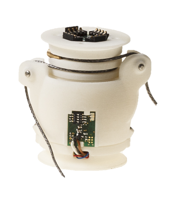
Material needed:
1 x Barrel-shaped housing
1x Lid; 1x Pivot shaft
2x Bearings 3802 15x24x7 mm
2x Securing pins 3mm x 8 mm
1 x Flat shaft screw M12 x 1
4 data wires 0,25 mm2
2 power wires highly flexible silicon 1,5 mm2
2 x connector boards, four spring contacts
8 x M1,6 x 6
7.3.1.2. Step 1: Mount sensor board
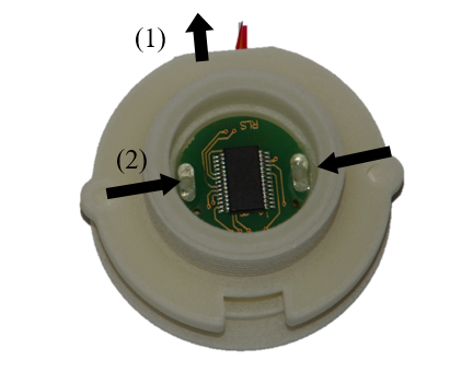
Push the sensor cables through the cable channel.
Place the sensor board on the pins and glue on two points.
Tips:
for pre fixation of the board melt the plastic pins with a soldering iron
7.3.1.3. Step 2: Mount pulleys and magnet
Put in the two pulleys.
Fix them with the pins.
Glue the magnet into the pivot shaft.
7.3.1.4. Step 3: Place the bearings into the housing
Place the two bearings into the barrel-shaped housing from below.
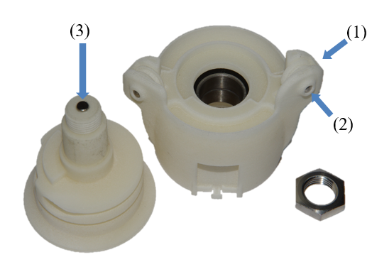
7.3.1.5. Step 4: screw the pivot shaft into the housing
Put the pivot shaft into the barrel-shaped housing and tighten the nut.
7.3.1.6. Step 5: screw lid on barrel-shaped housing
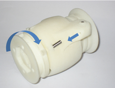
Screw the lid on the barrel-shaped housing and put in the security pin.
7.3.1.7. Step 6: Solder cables to the board

Prepare cable tree on connector boards.
Cut on 15 cm length:
4 data wires 0,25 mm2
2 power wires highly flexible silicon 1,5 mm2
Connector side:
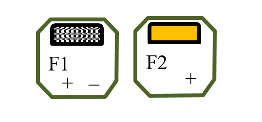
Pin colour code:
F1+ white
F1 - brown
F2 + yellow
F2 - green
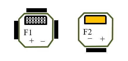
7.3.1.8. Step 7: Cable and solder cables to the second board
Place PCB carrier in SB
Solder cables to the second board (from below)
Carrier orientation:
Pin colour code:
F1+ white
F1 - brown
F2 + yellow
F2 - green
Push cable tree through the joint.
Screw both connector boards to joint with four M1,6 screws.
7.4. Type 4: Hinge-Pivot
This joint type provides 2 DoFs of rotation: one along an axis parallel to the proximal joint end plane (hinge) and one along an axis perpendicular to the distal joint end plane (pivot). The angular range of rotation of the hinge is symmetric with respect to the axis perpendicular to the structural bond. Both DoFs are implemented using a combination of axles and rotational bearings.
7.4.1. Variety 1
This implementation uses ball bearings for the hinge and pivot to reduce the friction and increase the efficiency of the joint. The tendon cables actuating the pivot part (in red hereunder) are running through the centre of the axles of the hinge part. The absolute joint angles are measured using Hall-effect sensors and magnet rings.
7.4.1.1. Illustrations
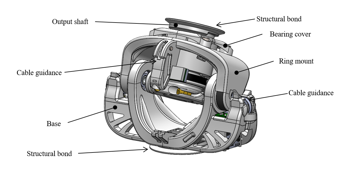
Fig. 7.8 Illustration of the Hinge-Pivot joint construction
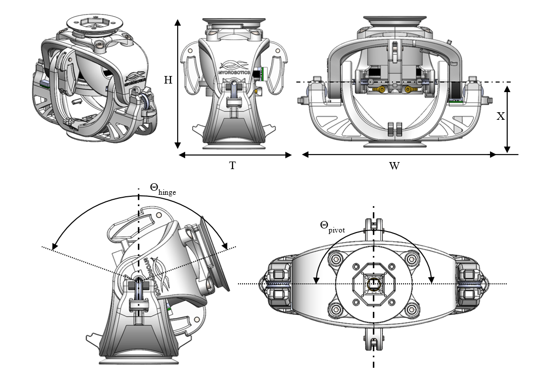
Dimensions
H Distance between joint end planes
W Maximal width of the joint
T Maximal thickness of the joint
X Height of the hinge rotation axis
Θhinge Motion range of the joint
Θpivot Motion range of the pivot
Implemented instances
Reference |
JOINT-SC2-T4-V1 |
||
|---|---|---|---|
Corresponding DP-Class |
II |
||
Dimensions |
H |
95 |
[mm] |
W |
142 |
[mm] |
|
T |
78,5 |
[mm] |
|
X |
47,5 |
[mm] |
|
Θhinge |
140 |
[°] |
|
Θpivot |
180 |
[°] |
|
M |
~300 |
[g] |
|
Features
Base:
It holds the bearings for the hinge.
Two mechanical stoppers limit the motion range of the hinge by contacting the ring mount.
The structural bond (SB) is integrated on the proximal side of the base.
It provides a fixation point on each side to screw a pulley-support.
Pulley-support:
This part holds a pulley redirecting one of the tendon cables actuating the pivot through the hinge axle.
Ring mount:
Two cable attachments (CA-SC2-T2) are provided, allowing the bidirectional actuation of the hinge.
It holds two angular ball bearings for the pivot.
It holds two pulleys that guide the tendon-cables for the pivot actuation towards the cable winch.
It holds the two axles of the hinge, which are inserted with interference fit.
The shafts are axially secured with steel sheets.
Each steel sheet is secured with a cover clipped on the ring mount.
A half magnet is mounted on its right side for the measurement of the hinge absolute position.
The electronic board with the sensor measuring the absolute position of the pivot is mounted on its back.
Cable winch:
Two tendon cable attachments are provided for the bidirectional actuation of the pivot and the round shape of the cable insures a constant lever arm.
A magnet ring is mounted on the cable winch to measure the pivot absolute position.
Output shaft:
The output shaft is mounted in the two angular ball bearings.
The structural bond (SB) is integrated on the distal end of the output shaft.
The cable winch is fixed to the output shaft with a screw with inner hole, allowing the passage of the electric cables.
Bearing cover:
The bearing cover covers the two angular ball bearings.
A mechanical stopper limits the motion range of the pivot.
It is assembled with four screws on the ring mount.
Sensor and electrical interfaces:
The sensor board for the hinge is attached on a pulley-support.
The sensor board for the pivot movement is attached on the HX-ring mount.
The cables routing (for the sensors) is supported by mounting clamps.
The cables between the electrical interfaces of the structural bonds are guided through the output shaft.
Material and fabrication
Element name |
Material |
Fabrication processes |
|---|---|---|
proximal base ring mount distal output shaft cable winch bearing cover pulley support axle cover safety cable cover cable cover pulley external pulley internal |
Polyamide (PA) |
|
axle |
Aluminium |
|
Sheet metal axle cover |
Steel |
|
Bearing |
Steel |
|
screws |
Steel |
|
Parallel pins |
Steel |
|
7.5. Type 5: Hinge-Hinge
The joint type is a combination of two hinge joints using a combination of axle and rotational bearing (principle II). It is provides 2 DoFs of rotation along two axes: the first parallel to the proximal joint end plane (proximal axis), the second parallel to the distal joint end plane (distal axis).
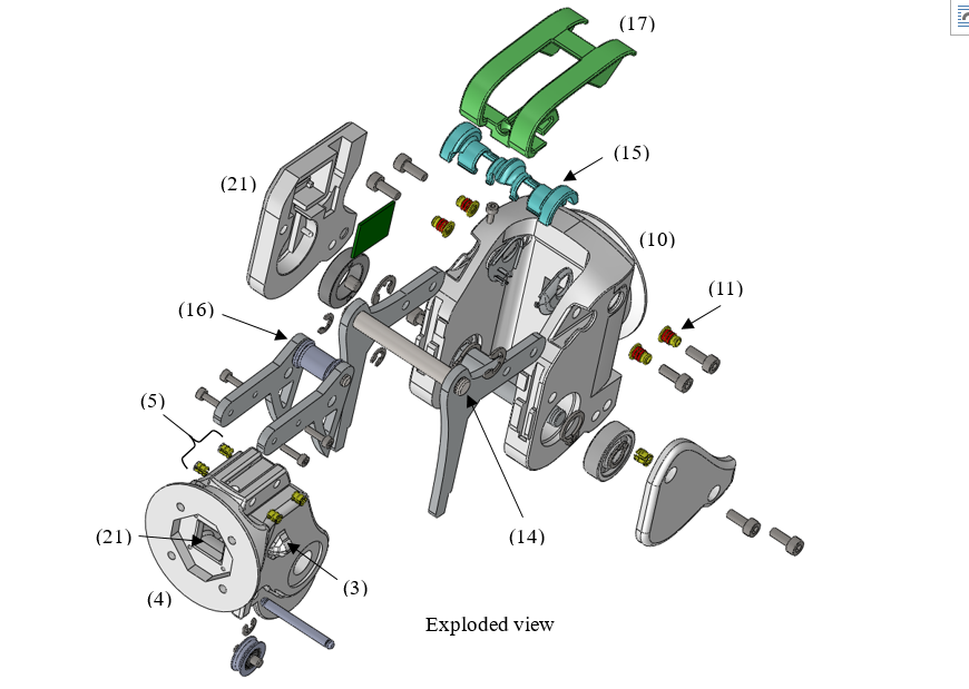
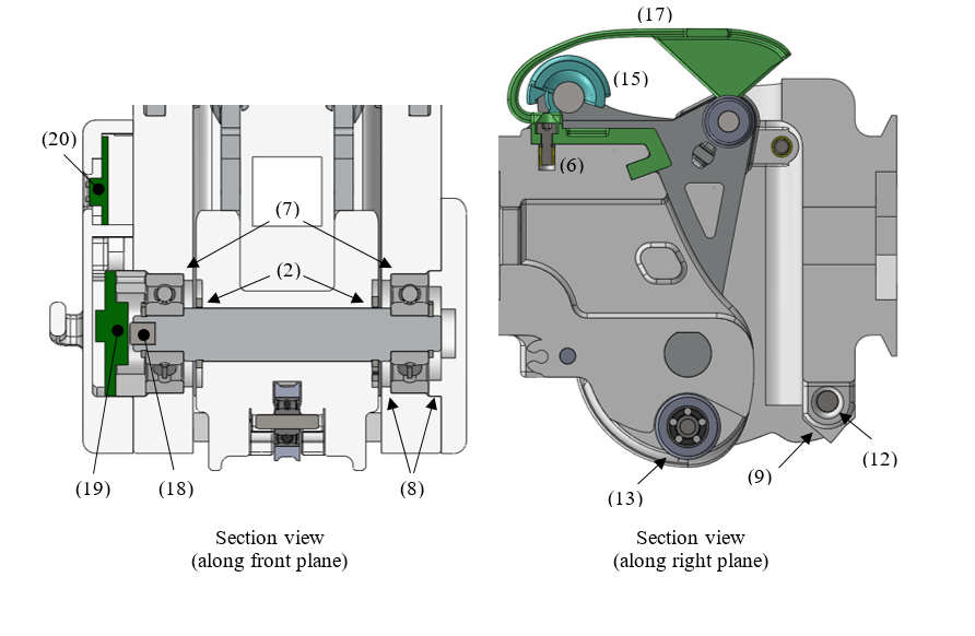
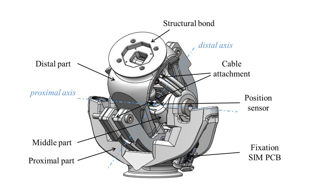
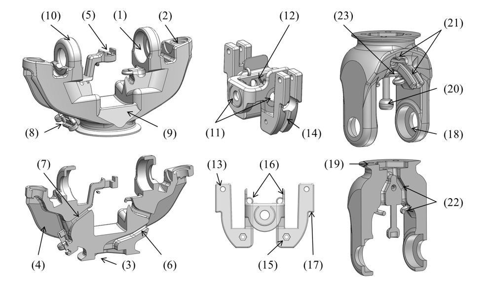
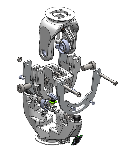
7.5.1. Variety 1: Universal Joint
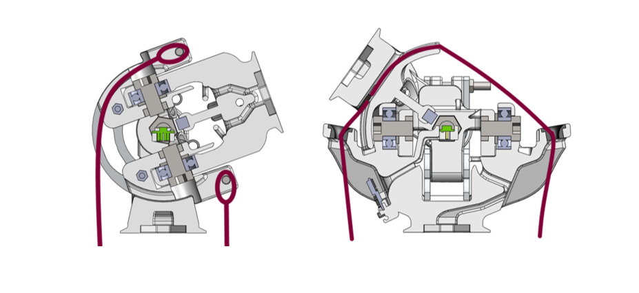
The two rotation axes intersect and are perpendicular. The joint is composed of three load carrying components: the proximal, middle and distal parts. The proximal and distal parts can be mounted to other toolkit elements via the modular structural bond. The middle part connects both sides and defines the plane for both axes. Each rotation axis is implemented using two symmetrical axles, which are made up of a screw, a plain washer, a nut and a bearing. The rotation around the proximal axis is actuated by two tendon cables fixed to screws on the middle part. The tendon cables that actuate the distal axis are guided by two ceramic bushes placed on each sides of the proximal part and their ends are attached on the distal part. Both rotations can be actuated independently and each tendon cable has an almost constant lever arm with respect to the rotation axis it actuates. The two absolute angles are measured with a position sensor located in the intersection point of both axes.
Illustrations:
Overview:
Individual elements:
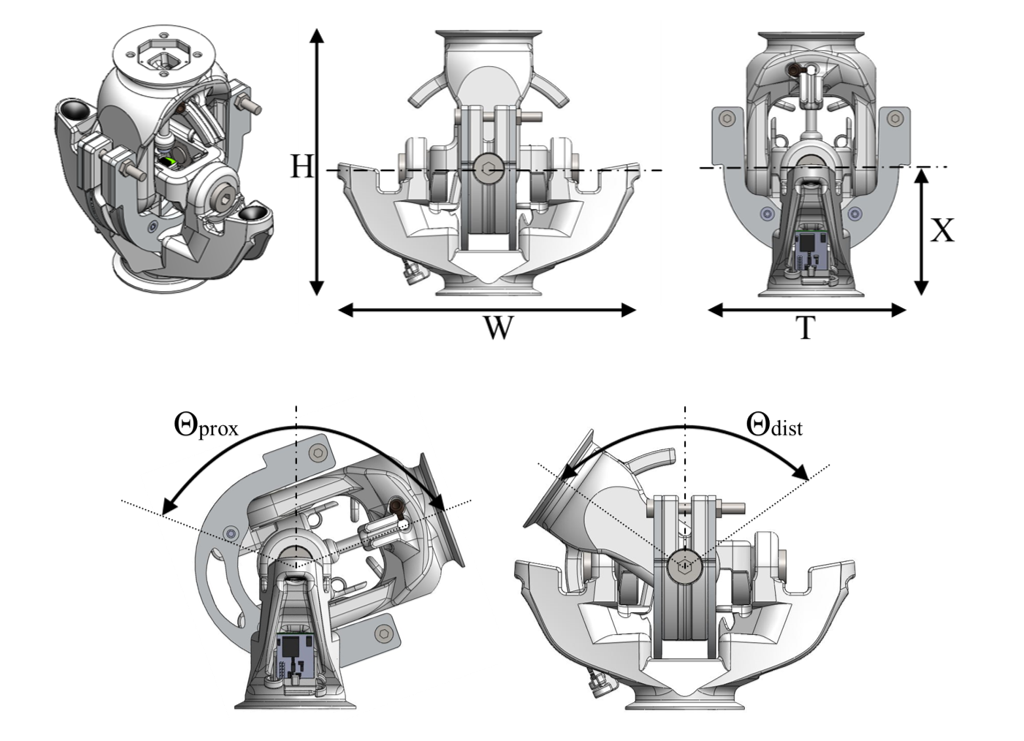
Dimensions:
H Distance between joint end planes
W Maximal width of the joint
T Maximal thickness of the joint
X Height of the proximal axis
Θprox Motion range of proximal rotation
Θdist Motion range of distal rotation
Implemented instances:
Reference |
JOINT-SC2-T5-V1 |
||
|---|---|---|---|
Corresponding DP-Class |
II |
||
Dimensions |
H |
115 |
[mm] |
W |
131,2 |
[mm] |
|
T |
86 |
[mm] |
|
X |
55 |
[mm] |
|
Θprox |
140 |
[°] |
|
Θdist |
110 |
[°] |
|
M |
~320 |
[g] |
|
Features:
Proximal part:
Two bearings and two screws are implemented in the proximal part.
Two ceramic bushes are implemented on the proximal axis of the proximal part.
The proximal structural bond (SB) is integrated on the proximal part.
The topology of the part from the SB to the joint axis and the ceramic bushes is optimized to the expected loads.
A bridge for attaching the position sensor (originally a joystick sensor) is located in the center of both rotation axes.
The cables coming from the proximal SB connection board are guided through a tunnel to the center of the joint.
The cables from the sensor are guided through a tunnel to the SIM board.
The part includes an emplacement on the side to attach the SIM board.
Mechanical stoppers, which collide with (17), limit the motion of range of the proximal rotation.
Mechanical stoppers, which collide with (23), limit the motion of range of the distal rotation.
Middle part:
The middle part holds the four axles (implemented using screws) together.
Hexagonal openings allow the insertion of nuts to screw the axles in place.
Cable attachments for the tendon cables actuating the rotation around the proximal axis are provided on the middle part, in the form of screws around which the tendon cables can be knotted.
The tendon cables are guided on a circular arc centered on the proximal axis with a constant lever arm to the MYO-Muscle.
Two aluminum sheets on each side of the circular arc reinforce the middle part, so that it is able to cope with the high forces applied by the tendon cables. Two distance spacers embedded in the middle part are used to screw the aluminum sheets.
Rings and walls inside the middle part guide the electric cables from the proximal part to the distal part
Mechanical stoppers, which collide with (9), limit the motion of range of the proximal rotation.
Distal Part:
Two bearings and two screws are implemented in the distal part.
The distal structural bond (SB) is integrated on the distal part.
A bar directed towards the center of the joint allows the attachment of the magnet used with the position sensor. The distance between the magnet and position sensor is constant.
Two cable attachments (CA-T2-DPX), allowing the bidirectional actuation of the rotation around the distal axis, and guides for the tendon cables are implemented.
Rings and tunnels guide the electric cables coming from the middle part to distal SB connection board.
Mechanical stoppers, which collide with (10), limit the motion of range of the distal rotation.
Material and fabrication:
Element name |
Material |
Fabrication processes |
|---|---|---|
Proximal part Middle part Distal part |
Polyamid (PA) |
laser sintering |
Aluminium sheets |
Aluminium |
water-jet cutting |
Bearing Screw Nut Plain washer |
Stainless Steel |
purchase (standard component) |
Ceramic bush |
Ceramic (polished surface) |
purchased |
Position sensor Magnet |
purchased |