6. MYO-Muscle
6.1. Type 0: Passive Muscle
In some cases, it is sufficient to have a passive muscle (i.e. without a motor to contact the muscle) acting as antagonist to an active muscle, in order to reduce the weight or the cost of the robot.
6.1.1. Variety 1 - Simple spring
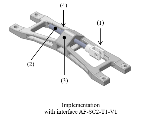
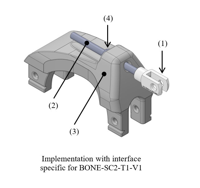
This is the simplest variant of the passive muscle. It consists of an attachment point, provided by a yoke (1) holding a pin to which a extension spring can be fixed, directly or indirectly via a tendon cable. The yoke if fixed to a threaded rod (2) so that the position of the attachment point with respect to the base (3) of the passive muscle can be adjusted by tightening or losing a single nut (4). This allows to adjust easily the length of the tendon cable and/or to adjust the joint position at which the spring starts to be loaded.
Illustrations
6.2. Type 1: Unilateral Series Elastic Actuator
This type of actuator is mainly made of the following elements:
a mechanical base to attach the actuator module to the bone
a geared DC motor
a series elastic element
a cable transmitting the force to the skeleton
6.2.1. Variety 1: Compression Spring
This implementation builds on the hardware developments achieved in the Roboy project, in which the MYOROBOTICS consortium members TUM and ETH are contributing. The series elastic element is a linear compression spring combined with a set of pulleys, to reproduce the characteristics of a non-linear progressive spring. The origin of this idea can be tracked back to [Hyodo1993] and has been implemented in different forms in various SEA and variable stiffness actuators.
Illustrations
Overview:
Individual elements:
Integration to BONE-SC2-T1-V1 (see Section 5.1.1.1):
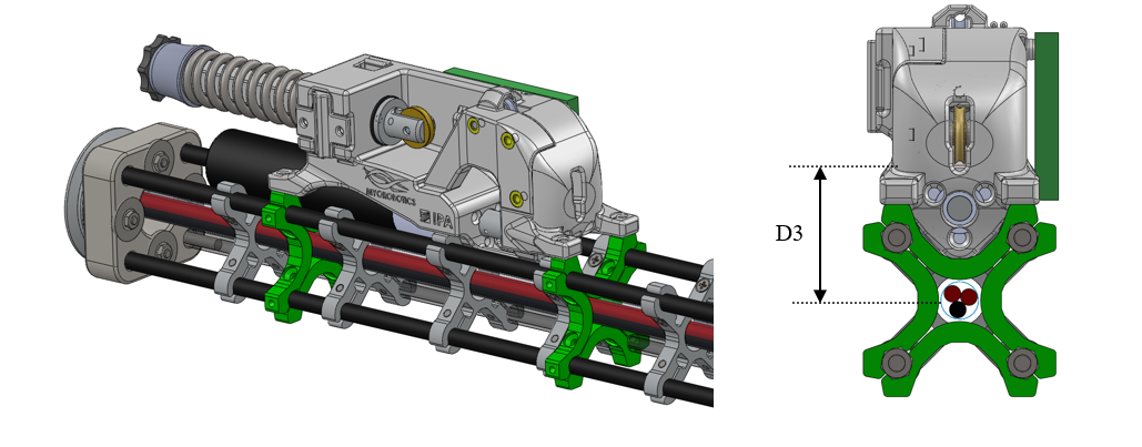
Dimensions
D1 Total length of the actuator
D2 Total height of the actuator
D3 Lever arm of the tension force in the cable w.r.t. the bone section centre
Implemented instances
Reference |
MUSCLE-T1-V1-P100W |
||
|---|---|---|---|
Corresponding DP-Class |
II & III |
||
Motor power |
100 W |
||
Dimensions |
D1 |
192 |
[mm] |
D2 |
60 |
[mm] |
|
D3 |
32 |
[mm] |
|
Features
Mechanical base:
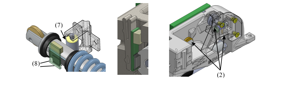
The mechanical base is connected to the bone using multiple anchor carriers developed for the BONE-SC2-T1-V1 (“Anchors circular pattern for vis-à-vis attachment”, see Section 5.1.1.1). As this implementation is based on an already existing hardware, it was not straightforward to directly use the available adaptor. For that reason one part of the adaptor was directly integrated in the mechanical base. Using the other parts of the anchor carrier (represented in green), the mechanical base can be fixed to the bone.
The mechanical base contains a set of pulleys that redirect the cable transmission, from the motor reel, via the series elastic element, to come out parallel to the bone longitudinal axis.
DC motor:
The DC motor is fixed to the mechanical base by a set of screws. It is equipped with an optical incremental encoder.
A cable reel is attached to the DC motor shaft to wind up the cable. It has a cable attachment (of type CA-SC2-T1) to attach one side of the cable and is supported by a bearing at its extremity.
The motor driver board (see hereunder) is fixed on one side of the mechanical base.
Series elastic element:
The series elastic element is based on a compression steel coil spring.
The spring compression is guided by a cylindrical plastic part, two bearings to slide linearly and a guide roller that prevents any twists. The other side of the spring is fixed using a spacer sleeve, a knurled nut and a nut witch are screwed together to a threaded rod witch is concentric to the cylindrical plastic part.
To measure the deflection of the spring, a hall sensor in combination with a magnetic strip is used. It measures the linear displacement of the cylindrical plastic part. The sensor board is fixed with a wedge-shaped clip that has a spring lock mechanism.
Cable:
Cables made of high performance polyethylene fibres (HPPE), also commercially referred to as Dyneema®, were selected for their high strength, light weight, low stretch and flexibility.
Material and fabrication
Element name |
Material |
Fabrication processes |
|---|---|---|
Mechanical base |
Polyamid (PA) |
laser sintering |
DC motor Bearings Pulleys |
purchase (standard component) |
|
Reel |
Aluminium |
machining |
Compression Spring |
Steel |
purchase (standard component) |
Cylindrical part |
POM |
machining |
Cable |
Dyneema® (HPPE) |
purchase (standard component) |
Integration of the electronics
Motor driver board (MDB):
This driver board is based on the dsPIC33FJ128MC802 from Microchip, a micro-controller particularly suited for motor control applications. The MDB includes a sensor for the motor current and inputs for additional sensors, such as the spring displacement. The MDB can communicate with the MYO-Ganglion via SPI and also has a CAN interface for stand-alone applications, debugging and configuration.
Accessories
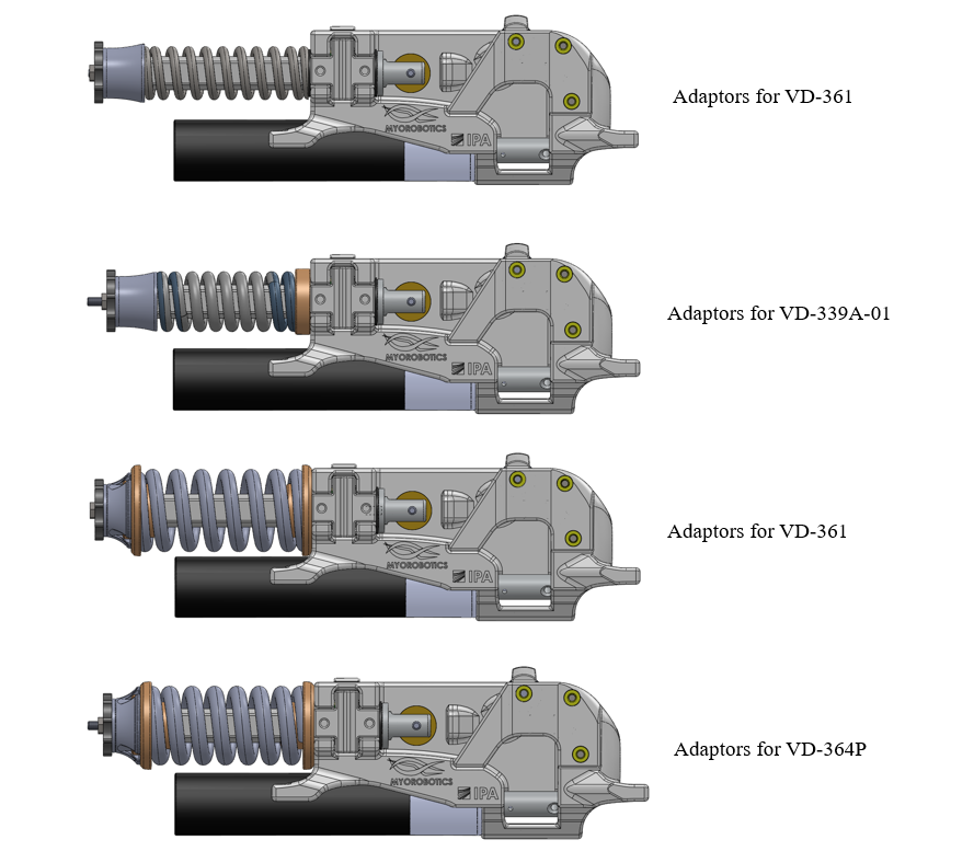
Spring adaptors
The mechanical base of the muscle was designed to allow the usage of various springs, as long as their dimensions are compatible with the spring guidance mechanism. The interface between the mechanical base and the spring guidance mechanism on one side and the spring on the other side is achieved by spring adaptors. The adaptors designed so far allow the usage of four springs with different stiffness and maximal forces selected from the catalogue of Gutekunst Feder.
Reference |
D-311 |
VD-339A-01 |
VD-361 |
VD-364P |
|---|---|---|---|---|
Stiffness R (N/mm) |
30,682 |
64,301 |
63,636 |
127,805 |
Maximal force F n (N) |
664,58 |
813,639 |
1191,193 |
1337,561 |