2. Introduction
Danger
This control section describes the old MYODE architecture. While most parts of the hardware and firmware are unchanged, the high-level control is very different. The remaining, valid information will be incorporated into the above section.
A heterogeneous distributed control architecture has been developed to allow the modular configuration and control of compliant muscolosceletal robots. This architecture has been designed specifically to facilitate further research into the control of highly coupled muscolosceletal robotic systems by removing the initial hardware development phase required to undertake such research. Toward this end, the embedded control architecture sustains a transparent interface between the physical design primitives (joints, links, muscles and sensors) and a PC based simulation, development and test environment (Caliper and MYODE). This report provides a comprehensive description of the component parts that make up the release version of the control architecture and provides testing results of the various operational modes that it supports. It is intended that this page will serve as a technical reference manual for end users to understand the system, visualise its performance and appreciate its constraints.
Tis page is composed of 3 sections; A technical description of the various components that make up the control architecture; A comprehensive guide to the connectivity between components necessary to build a MYO-Robot; and finally a collection of integrated test results that have been designed to demonstrate the performance and capabilities of the system in a number of robot control scenarios.
3. Hardware Description
Danger
This control section describes the old MYODE architecture. While most parts of the hardware and firmware are unchanged, the high-level control is very different. The remaining, valid information will be incorporated into the above section.
3.1. Principles
The Myorobotic control system comprises four main components. The highest level of the control system is formed by the Caliper environment and the associate MYODE plugin suite. Caliper and the MYODE plugins are software applications that run on Ubuntu 12.04 and communicate with the rest of the control system via a 10Mbit/s FlexRay bus. The FlexRay bus forms the back-bone of the Myorobotics communication infrastructure. Along the robot’s FlexRay bus, up to six MYO-Ganglions can be attached. The MYO-Ganglions are local control and communication units. Each MYO-Ganglion can control up to four MYO-Muscles in various control modes. Each MYO-Muscle has its own motor driver unit, and communication with the MYO-Ganglion is achieved via a 2 Mbit/s SPI interface. In addition, each MYO-Gangion has up to four joint angle sensors attached to it. They communicate on a shared 1 Mbit/s CAN bus with the MYO-Ganglion. This CAN bus is also shared with up to 12 MYO-receptors, external sensors that can provide various external values to the Myorobot, e.g. pressure, temperature etc. The message (or sampling) rate of the joint sensors is \(1\frac{message}{ms}\), the MYO-Receptors only provide their sensor status every 10ms. This asymmetry allows good utilisation of the CAN bus, whilst guaranteeing a sufficient update rate for the joint angles, important for their control.
An overview of the communication and control infrastructure is given in Fig. 3.35. In the following sections, we will introduce and describe the relevant subsystems and explain how the several linear control schemes are implemented.
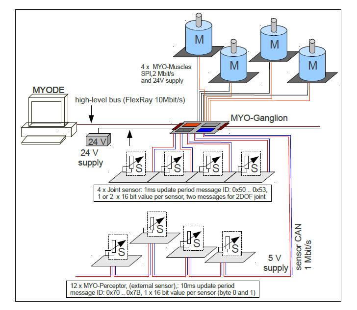
Fig. 3.35 Overview of the heterogeneous Myorobotics control infrastructure.
3.2. Modules
3.2.1. MYO-Ganglion
Danger
This control section describes the old MYODE architecture. While most parts of the hardware and firmware are unchanged, the high-level control is very different. The remaining, valid information will be incorporated into the above section.
The MYO-Ganglions are main control and signal processing units, distributed along the robots links. They are based on the TMS570LS20216, a 32-bit floating point digital signal processor from Texas Instruments. This micro-controller is based on their ARM Cortex RISC CPU, provides analogue and digital I/O and several relevant communication interfaces. The 140MHz clock and the floating point unit enable high-performance signal processing and control algorithms to be implemented. Together with the appropriate motor drivers (see section Section 3.2.3), a MYO-Ganglion is able to control up to four actuators. Fully transparent access to motor and sensor data from MYODE is possible through the integrated 10Mbit/s FlexRay interface, using a ’FlexRay typical’ 1ms control loop. At this communication rate, up to 24 MYO-Muscles are controllable using six MYO-Ganglions on each FlexRay bus. Each ganglion is assigned a fixed communication ID (Ganglion ID) in the range from 0 to 5. Currently this is achieved during the programming of the on-chip Flash memory. In the next instantiation of the MYO-Ganglion, a small bank of DIP switches will allow the end user to configure the Ganglion ID. As a consequence, all MYO-Ganglia can run on the same software and no re-programming is necessary for high-level users. Similarly, an additional bank of DIP switches will allow the user to configure how many motor driver boards are connected to the MYO-Ganglion.
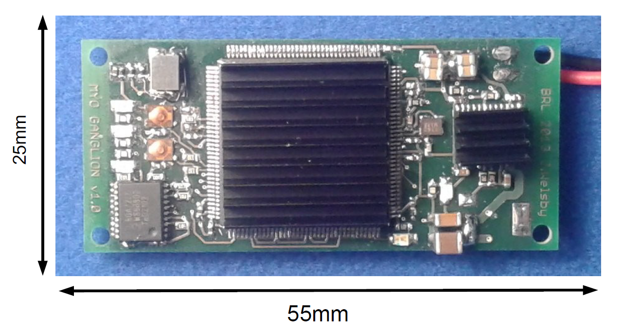
Fig. 3.36 The MYO-Ganglion hardware, a densely packed 4 layer printed circuit board (communication connectors below). Heatsinks are mounted on the microcontroller and the multi-voltage regulator. Size: \(\approx 25mm \times 55mm\).
In addition to the FlexRay interface, the MYO-Ganglion provides a CAN communication bus (1 Mbit/s) to allow the connection of joint angle sensors (Section 3.2.2) and MYO-Perceptors, the external sensors (Section 3.2.5). Communication to the motor driver boards is established with four [1] dedicated SPI links, each running at 2 Mbit/s.
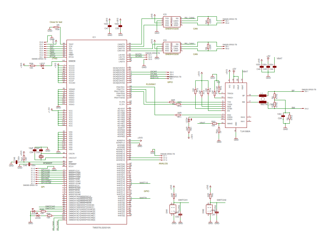
Fig. 3.37 Circuit diagram of the MYO-Ganglion (without power supply).
3.2.2. Joint Angle Sensor Board (JASB)
The position of each joint is measured using a joint angle sensor that communicates with the MYO-Ganglion on a shared 1Mbit/s CAN bus. This printed circuit board, that interfaces with the actual sensor, is based on the dsPIC33FJ128GP802 from Microchip. It is supplied with 5V DC and communicates with the MYO-Ganglion CAN bus (see Fig. 3.35). The actual joint sensor can be a simple potentiometer or a hall-effect based absolute position sensor. Any of those sensor is supplied with 3.3 V from the JASB and must provide an analogue output.
The joint angle interface board senses joint angles on analog input zero and one (AN0, AN1). This information, encoded as a 12-bit unsigned integer in byte 0 and 1 (little endian), is broadcast on the CAN bus every 1ms. The CAN message ID (MsgID) can be adjusted with the 2 DIP-switches (on switch bank SW2) beween 0x50 and 0x53, using switch 1 (S1) (lsb) and switch 2 (S2) (msb). In order to configure the sensor board for 1DOF, switch 3 (S3) needs to be off. For 2DOF operation, S3 needs to be on. With S6 the CAN termination can be switched on (1) or off (0). S4 is used for joint calibration and needs to be in the off position during normal operation, see below.
In case of 1DOF operation, only one CAN message with the MsgID indicated by switches S1 and S2 is sent. For 2DOF operations, two CAN messages are sent, the first one has the MsgID indicated by switches S1 and S2, the second CAN message has the ID indicated with switches S1 and S2 plus 1.
S1 |
S2 |
S3 |
messageIDs on bus |
|---|---|---|---|
0 |
0 |
0 |
0x50 |
0 |
0 |
1 |
0x50 and 0x51 |
0 |
1 |
0 |
0x51 |
0 |
1 |
1 |
0x51 and 0x52 |
1 |
0 |
0 |
0x52 |
1 |
0 |
1 |
0x52 and 0x53 |
1 |
1 |
0 |
0x53 |
1 |
1 |
1 |
0x53 |
The DIP switches (S1, S2 and S3) are read after power-on reset. Manipulation of the switches during operation has no effect. The analogue inputs are 16 times oversampled (16kHz) and the CAN output data is the moving average of the last 16 measurements.
LED1 on the sensor board blinks at 1 Hz, indicating operation. LED2 blinks as a function of the AN0 value, the lowest frequency is 1Hz, the highest frequency is 500Hz (AN0=0). In other words, a low frequency (i.e. a large period) corresponds to a large AN0 reading. This allows simple visual inspection of the operation of the joint sensor. LED3 is only on when the board is connected to a non-functioning CAN bus, i.e. the red LED is on during various CAN error states. In a CAN error state, LED1 and LED2 only function correctly when in 1DOF mode.
3.2.2.1. Calibration
The mounting of the magnetic position sensor can lead to a situation where the output signal experiences a zero-crossing (over or underflow) when the joint goes through its motion range. This is not desirable and it is therefore possible to calibrate this out of the joint. This is a software process and no mechanical manipulation. This calibration only has to be performed once, the calibration values are stored in the EEPROM/FlashMemory of the JASB microcontroller. The calibration can be repeated if necessary. Procedure:
adjust S1, S2 and S3 according to joint configuration (i.e. address and DOF).
power joint up.
put S1 and S2 to off, S3 can remain in current position.
switch S4 on.
move joint in negative direction until at end stop, hold in position and flick S1 on and off again.
move joint in positive direction until at end stop, hold in position and flick S2 on and off again.
joint end positions are now stored, flick S4 back to off to write position into EEPROM/FlashMemory.
bring S1 and S2 back to correct address position.
calibration has been performed and joint angle measurement values will now move through continuous range without zero-crossing or overflow.
When calibrating a 2DOF joint, move both degrees of freedom to there negative and positive end position at the same time when performing this calibration procedure.
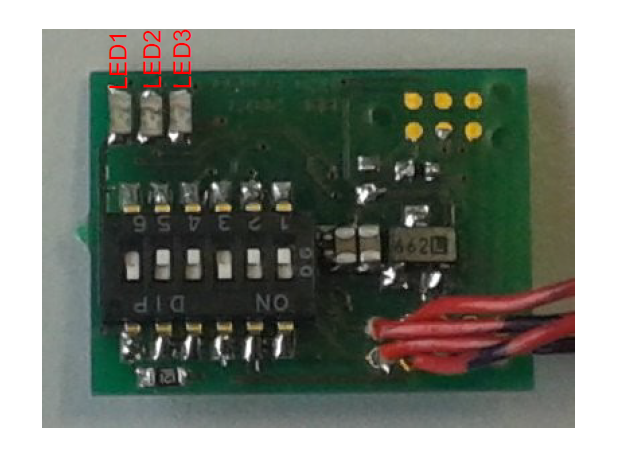
Fig. 3.38 Top View of the joint angle sensor board: LED1, LED2 and LED3 indicate basic functionality, sensor reading on AN0 and CAN error states. Size: \(\approx 14mm \times 19mm\)
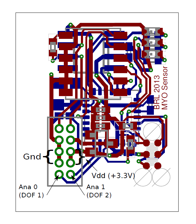
Fig. 3.39 Joint sensor angle board PCB layout to illustrate sensor connections.
3.2.3. Brushless-DC Motor Driver
The MYO-Muscles are (at this stage of the project) series elastic actuators, driven by brushless DC motors from Maxon. In order to drive these motors (for different size categories) a driver board was developed. This driver board is based on the dsPIC33FJ128MC802 from Microchip, a micro-controller particularly suited for motor control applications.
In brief, the functionality of the motor driver board is as follows:
Commutation: only 3-phase brushless DC motors can be driven. Commutation feedback from the motor via hall-effect sensors is required.
Position feedback: The motor shaft position can be sensed via an incremental encoder interface with differential inputs. The microcontroller is configured in \(4 \times\) - mode, e.g. a shaft rotation with an encoder of 512 pulses/rotation will increment the internal encoder counter by 2048.
For our medium sized MYO-Muscles the motor assembly has an encoder with 512 counts/rotation. In addition the motor output shaft is driven via a 1:53 gear box. Consequently, the output shaft resolution is \(r_{output}=512 \times 4 \times 53 = 108544 \mbox{ } counts/rotation\)
Spring Displacement: The spring displacement (indicating the tendon strain) is sensed via a magnetic strip and a hall-effect based sensor. The magnetic strip (for illustration pictured below) provides magnets with a distance of 2.4mm between pole pairs. The sensor provide 40 encoder pulses per magnet (pole pair).
The sensor provides an incremental encoder interface which is read by the micro-controller. Similar to the motor shaft position feedback, the encoder interface is configured in \(4 \times\) - mode, so that resolution is of \(\frac{2.4 mm}{40 \times 4} = 15 \mbox { } \mu m/count\) , i.e. \(r_{displacement}=66.\overline{6} \mbox{ }counts/mm\).
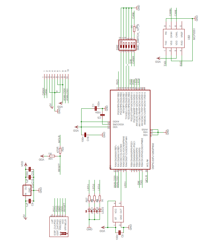
Fig. 3.40 Circuit diagram of the joint angle sensor interface board.
Fig. 3.41 Brushless-DC motor driver board. Size: \(\approx 40mm \times 55mm\)
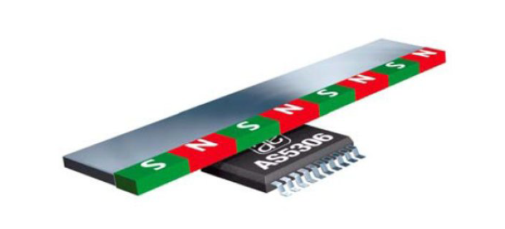
Fig. 3.42 Operational principle of the spring displacement sensor using the AS5306 from AMS.
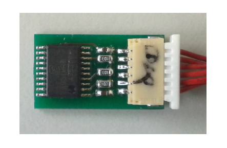
Fig. 3.43 Circuit board with the spring displacement sensor, the AS5306 from AMS.
Motor current: The motor current is sensed via two shunt-resistors, one in phase A and one in phase B of the motor. For the medium sized motors, \(10m\Omega\) resistors are used as shunts. A differential amplifier gains the voltage drop on the resistors by a factor of 20 and the output of the amplifier supplies the ADC of the microcontroller.
With 10-bit ADC, supplied by a \(3.3V\) reference, the sensed and amplified current is represented as an integer in a range between \([0..1023]\). The resistor-amplifier arrangement has a gain of \(G_{RA} = 0.01 \frac{V}{A} \times 20 = 0.2 \frac{V}{A}\). The ADC gain is \(G_{ADC}=\frac{1024 \mbox{ } counts}{3.3V} = 310.\overline{30} \frac{counts}{V}\). Taken together, the ADC gain for the current measurement is
In other words, the smallest current that can be measured is \(1 /( 62.\overline{06} \frac{ \mbox{ }counts}{A}) =16.11 \mbox{ }mA\).
SPI communication: The motor driver boards communicate with the MYO-Gangion with a 3-wire SPI interface. The MYO-Ganglion is the bus master and communicates motor control parameters to the motor driver boards. The motor driver board supplies the MYO-Ganglion with shaft position, shaft velocity, motor current, spring displacement and various error codes. Details of this communication protocol can be found in Section 4.
CAN communication: For testing and de-bugging but also in order to use the motor driver board in different applications, a 1Mbit/s CAN interface has been implemented. This non-essential communication interface is not described further in this page.
3.2.4. Power and Communication Distribution
In order to distribute power and communication signals from MYO-Bone to MYO-Bone as well as connecting motor drivers and sensor to the MYO-Ganglion, a distribution circuit has been designed. This printed circuit board sits inside the MYO-Bone and can be wired-up by the Myorobotics users.
3.2.5. MYO-Perceptor
The MYO-Perceptors have not been finalised at this stage, since they form an optional part, not relevant to the core control infrastructure. However, as mentioned above, they will be similar to the joint angle sensor and will communicate with the MYO-Ganglion via a CAN bus with a message rate of 100Hz, i.e. they distribute their state every \(10ms\). We envisage simple tactile sensors, temperature sensor etc. From an electronics design point of view, this constitutes a simple modification of the joint angle sensor board.
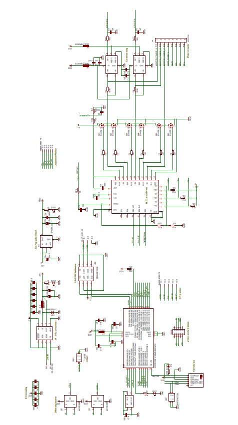
Fig. 3.44 Circuit diagram of the brushless-DC motor driver.
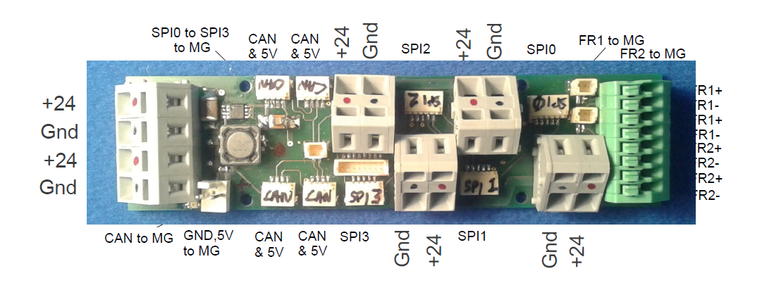
Fig. 3.45 Printed circuit board for power and communication distribution.
3.3. Connectivity
In order to connect motor drivers, MYO-Ganglions, spring displacement sensor and joint angle sensors, various cable connections are required. The connections between the boards are not 1 to 1 and not all connecting cables are symmetric, i.e. it is important which connector goes where. In the following, details of the connector cables are given.
3.3.1. Spring Displacement Sensor \(\Longleftrightarrow\) Motor Driver Board
Signal Name |
GND |
EncA |
EncB |
O |
Idx |
+5V |
|---|---|---|---|---|---|---|
Displacement Sensor, pin # |
1 |
2 |
3 |
4 |
5 |
6 |
Motor Driver Board, pin # |
5 |
3 |
2 |
1 |
4 |
6 |
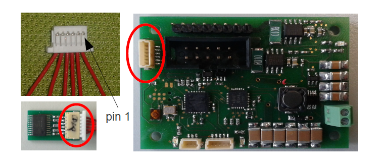
Fig. 3.46 Cables and connectors to connect the spring displacement sensor with the motor driver board; red circles mark the applicable connectors on the printed circuit boards.
This cable is not symmetric!
3.3.2. SPI: Distribution Board \(\Longleftrightarrow\) Motor Driver Board
Signal Name |
SOMI |
SIMO |
Clk |
SS |
Gnd |
|---|---|---|---|---|---|
Distribution Board, pin# |
1 |
2 |
3 |
4 |
5 |
Motor Driver Board, pin # |
1 |
2 |
4 |
3 |
5 |
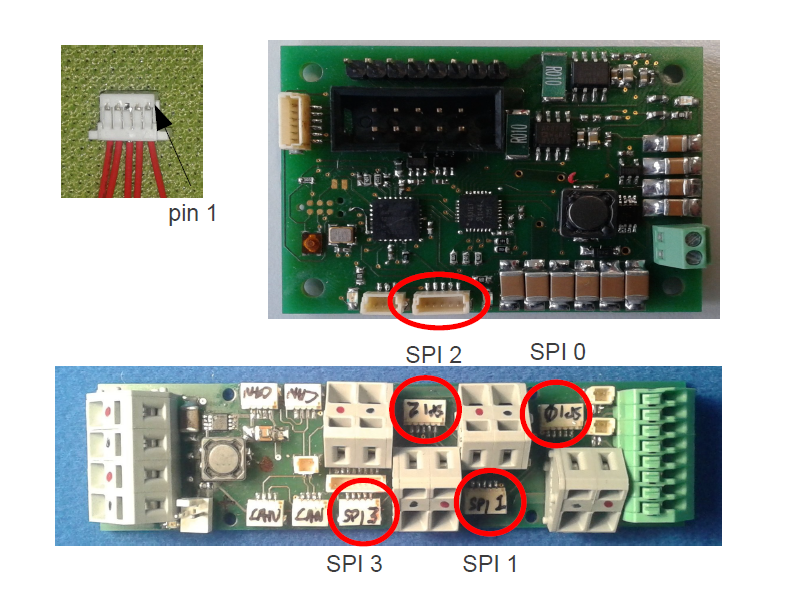
Fig. 3.47 Cables and connectors to connect the SPI of the distribution board with the motor driver board; red circles mark the applicable connectors on the printed circuit boards.
This cable is symmetric!
3.3.3. SPI:MYO-Ganglion \(\Longleftrightarrow\) Distribution Board
Signal Name |
SOMI |
SIMO |
En |
CS2 |
CS1 |
CS0 |
Clk |
Gnd |
|---|---|---|---|---|---|---|---|---|
MYO-Ganglion, pin# |
1 |
2 |
3 |
4 |
5 |
6 |
7 |
8 |
Distribution Board, pin # |
8 |
7 |
6 |
5 |
4 |
3 |
2 |
1 |
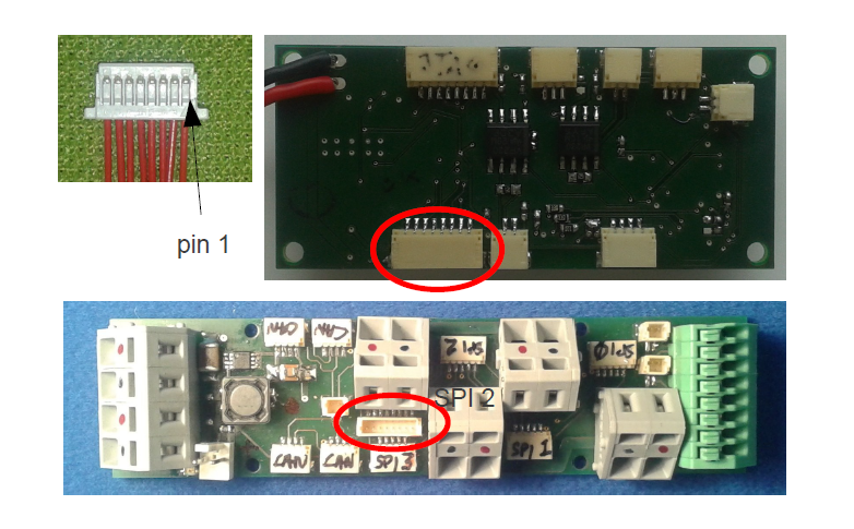
Fig. 3.48 Cables and connectors to connect the SPI of the distribution board with the MYO-Gangion; red circles mark the applicable connectors on the printed circuit boards.
This cable is symmetric!
3.3.4. CAN 1: MYO-Ganglion \(\Longleftrightarrow\) Distribution Board
Signal Name |
CAN-H |
CAN-L |
|---|---|---|
MYO-Ganglion, pin# |
1 |
2 |
Distribution Board, pin # |
2 |
1 |
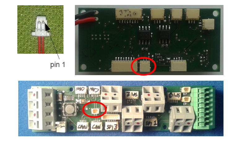
Fig. 3.49 Cables and connectors to connect the CAN of the distribution board with the MYO-Gangion; red circles mark the applicable connectors on the printed circuit boards.
This cable is symmetric!
3.3.5. FlexRay 1: MYO-Ganglion \(\Longleftrightarrow\) Distribution Board
Signal Name |
BP |
BM |
|---|---|---|
MYO-Ganglion, pin# |
1 |
2 |
Distribution Board, pin # |
2 |
1 |
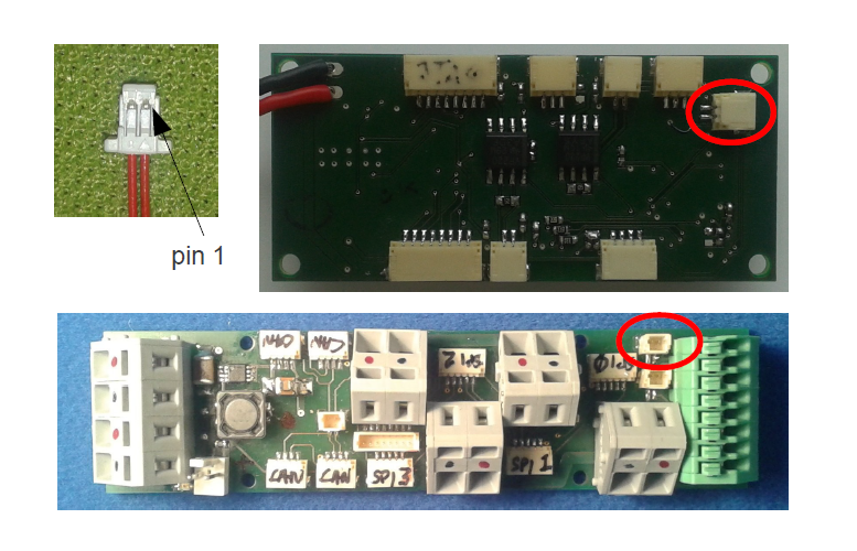
Fig. 3.50 Cables and connectors to connect the FlexRay of the distribution board with the MYO-Gangion; red circles mark the applicable connectors on the printed circuit boards.
This cable is symmetric!
3.3.6. Joint Angle Sensor Board \(\Longleftrightarrow\) Distribution Board
Signal Name |
CAN-H |
CAN-L |
Gnd |
+5V |
|---|---|---|---|---|
Sensor board, pad # |
1 |
2 |
3 |
4 |
Distribution Board, pin # |
3 |
2 |
1 |
4 |
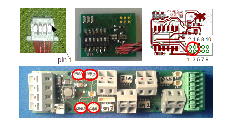
Fig. 3.51 Cables and connectors to connect the joint angle sensor board to the e distribution board; red circles mark the applicable connectors on the printed circuit boards.
3.3.7. Magnetic joint sensor \(\Longleftrightarrow\) Joint Angle Sensor Board
The magnetic joint sensor are soldered straight into the soldering pad on the joint angle sensor boards.
Signal Name |
Gnd |
Gnd |
+3.3V |
+3.3V |
AN0 |
AN1 |
|---|---|---|---|---|---|---|
Sensor board, pad # |
5 |
7 |
6 |
8 |
9 |
10 |
magnetic sensor cable colour |
blue |
orange |
red |
red |
green |
white |
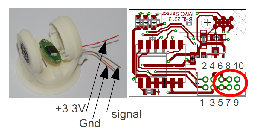
Fig. 3.52 Colour codes and pad number for connecting the magnetic angles sensors with the joint angle sensor board; red is +3.3 V, orange is Gnd and white is the sensor signal output. For 1DOF only AN0 is supplied with a sensor output, for 2DOF AN0 and AN1 are supplied with one sensor output each. Make sure to solder the opposite side to the red wires that go to the distrbution board (see 2.3.6).
4. Software
Danger
This control section describes the old MYODE architecture. While most parts of the hardware and firmware are unchanged, the high-level control is very different. The remaining, valid information will be incorporated into the above section.
The core of the operation of the controller infrastructure is software running on a network of MYO-Ganglions, combined with supporting tasks running on sub-networks of motor drivers and exteroceptive sensors. Each MYO-Ganglion can control up to 4 motors via an SPI communication bus, and can be provided with real-time commands direct from the Caliper environment via a high speed FlexRay bus, which also allows the MYO-Ganglions to relay all sensor information to the MYODE plugins. Exteroceptive sensors can communicate directly with each MYO-Ganglion via a local (to each MYO-Ganglion) CAN bus.
The software system is made up of a number of interacting sub-components which will be described in the following sections: communication, consisting of well defined protocols for each communication network; sensor access, what sensor information is gathered by each component in the system, and how that data is processed; motor drivers, the software running on each motor driver board; controller, the software structure that is used for the controllers, including the simple to use, user extensible, API; controller commands and tuning, the messaging structure used to allow the MYODE plugin suite to command and tune the controllers.
4.1. Communication
Communication between a MYO-Ganglion and up to 4 motor driver boards is performed using an SPI bus. In each communication cycle the MYO-Ganglion sends a duty cycle period demand and some command data, and receives the sensor values for the muscle it is actuating in return. The data structure for the SPI message frame is shown in Fig. 4.13. There are two types of message that can be sent to a motor driver, command and diagnostic. Command is the standard motor command, while diagnostic requests that the motor driver uses the standard data fields to report diagnostic data for error handling (instead of sensor data). The command flags allow requests for specific operations to be performed by the motor controller. The sensor data relayed via SPI is that which is directly related to the motor, i.e., motor position, velocity, drive current, and displacement in the series elastic element connected; additionally, provision has been made for two additional sensors to allow communication of possible further data from each motor driver board. The error flags field allows the motor driver to report error conditions to the MYO-Ganglion, error handling is then performed by the MYO-Ganglion, and dependent on the error message this might also trigger a diagnostic message to be sent in the next communication cycle to allow full error analysis and reporting.

Fig. 4.13 Data structure of an SPI data frame. The MYO-Ganglion transmits data in the first 4 elements, the others are used to trigger data transmission by each motor driver.
Each MYO-Ganglion has 2 CAN channels, one designed to allow the user to interface directly with the controller for debugging and initialisation of the FlexRay parameters, and the other for connection of ’smart’ exteroceptive and joint sensors that have their own microcontroller to allow communication over CAN. It is anticipated that, when implemented, these sensors will communicate with their attached MYO-Ganglion at a frequency of at least 1kHz. The framework for both of these tasks is included in the MYO-Ganglion API but specific uses of these facilities have yet to be developed.
In order for the control of a Myorobotics assembly from Caliper to be transparent to the user, a high speed FlexRay bus is utilised to relay control commands to each MYO-Ganglion, and for the MYO-Ganglia in turn to report their sensor information to the MYODE suite. In addition controllers and controller parameters that have been optimised in MYODE can be easily loaded onto each MYO-Ganglion.
FlexRay is a deterministic, high speed bus system (operating at 10MBit/s), in each communication cycle there is a static segment of predetermined frames for regularly transmitted data, and a dynamic segment for occasionally transmitted data. In a MYO-Ganglion network, the static segment is used for command and sensor data, and the dynamic segment for updating controller parameters; the dynamic segment is also used for fault reporting by the MYO-Ganglions.
All static frames must be the same size, and the largest (and most prevalent) frame type is the sensor data frame, the composition of which is shown in Table 4.2. Each static frame is sized to allow a MYO-Ganglion to transmit sensor data for up to 4 muscles, including the possibility of 1 joint per muscle (muscle 0 reports data for joint ID 0x50, muscle 1 joint ID 0x51 etc.), and 12 16-bit words [2] for exteroceptive sensor data. This data plus the FlexRay message header amounts to 48 16-bit words, and as we are aiming for a baseline control loop of 1ms, this allows transmission of 8 static frames, with a dynamic segment of 114 words (2 word times are required for the network idle time used in bus clock synchronisation). Allowing for 32-bit set point values, 4 of which may be required per MYO-Ganglion, commands for up to 6 MYO-Ganglia can be contained in one static frame. The MYODE suite requires an additional static frame to provide mode control commands for the controllers on each MYO-Ganglion, which may be indicators of the presence and purpose of data in the dynamic frame (see Section 4.4). Hence, up to 6 MYO-Ganglia may be commanded with a 1ms refresh rate, allowing the control of up to 24 muscles, the structure of data in a communication cycle is shown in Fig. 4.14.
Data |
Size (Words) |
comment |
|---|---|---|
Joint Position |
2 |
|
Actuator Position |
2 |
|
Actuator Velocity |
2 |
|
Actuator Current |
1 |
|
Tendon Displacement |
1 |
|
Total per Muscle |
8 |
|
Total Muscle Data |
32 |
4 muscles per MYO-Ganglion |
External Sensors |
12 |
per MYO-Ganglion |
Frame Overhead |
4 |
|
Total per Ganglion |
48 |
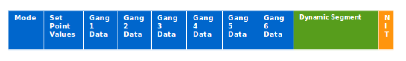
Fig. 4.14 Structure of a FlexRay communication cycle. Static frames are shown in blue, the dynamic segment is shown in green, and network idle time in orange.
4.2. Motor Drivers
4.3. Controller
The MYO-Ganglion controller API is written in C++, to allow both simple user extensibility and a single set of API functions to intuitively command a controller regardless of the underlying processes. However, it is important to note that as the interrupt service routines are written in C, a set of bridging functions are provided to allow them to access the underlying controller objects. The operation of the bridging functions requires that the underlying controller objects must all inherit a parent controller class, and implement its core set of (pure virtual) functions. These functions allow the getting and setting of the controller type and parameters (utilising a controller parameters union), and the invocation of the control loop with the desired set point (\(sp\)) and current process variable (\(pv\)) values.
A MYO-Ganglion has an array of controller objects, containing a controller for each available control mode, for each motor connected to it. Which controller is active for each motor is determined by part of the command in the controller mode frame (see Section 4.4). Each motor has an independent control loop frequency, and each iteration (if the currently selected controller is enabled) it calculates the needed demand signal to be sent. In the core API we have implemented linear feedback PID controllers, which are used to control a variety of process variables, as well as a raw control mode that allows direct setting of the motor driving PWM duty cycle. Each process variable is calculated from the raw sensor data provided by the motor driver board, to allow transparent tuning of PID gains via MYODE; the implemented process variable controllers, and their conversion factors are described in Table 4.3. The means for user extensibility of the controller infrastructure is detailed in the API documentation.
Process Variable |
Conversion Factor |
|---|---|
Actuator Position |
Rad/Encoder count |
Actuator Velocity |
Rad/Encoder count and control loop frequency |
Actuator Force |
Torque Constant |
Tendon Strain |
4 term polynomial |
In order to increase the safety of operation, the user is able to set limits for both the output drive signal, and the process variable demand, for each controller. These limits are included within the parameter set for each controller, and must be set during controller initialisation and parameter updates. Safe limits should be automatically generated by MYODE, or set by the user, during specification and simulation of a Myorobotics assembly, so that they can be loaded on to each MYO-Ganglion. The limits are enforced by each controller, and commands that try to exceed them will be limited to prevent them from doing so and generate fault messages transmitted as a dynamic frame. As an additional safety precaution controller, output is always checked against maximum drive values for the connected MYO-muscle to prevent user set limits from allowing maximum drive values to be exceeded.
4.3.1. Linear Feedback Controller Implementation
The linear feedback controller we have implemented on the MYO-Ganglion is a PID controller, with an additional feed-forward term using the desired set-point (sp), and optional dead-band and integral wind-up limiting. The gain for each control term (pgain, igain, dgain, forwardgain) must be set on controller initialisation and can be tuned during robot operation via MYODE; some process variables may not require all terms, and in this case the gain of unused terms is set to zero. Limits (\(outputPosMax\) and \(outputPosMax\)) for the control output are used to ensure safe operation.
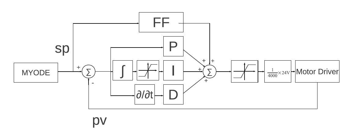
Fig. 4.15 Block diagram of the linear feedback controller: note the amplifier gain of \(\frac{1}{4000} \times 24V\).
These control limits are also used to limit integral saturation, by not adding to the accumulated integral on a control loop iteration when the output is in saturation and a control error is still present. Integral wind-up is implemented with thresholds (IntegralPosMax and IntegralNegMax) beyond which the integral cannot be increased. The symmetric dead-band is implemented similarly with minimum error thresholds (\(deadBand\) and \(-1\times deadBand\)) required to trigger a change in control effort. To ensure jerk-free operation when switching between control modes, the integral term is reset to zero when control modes are changed.
4.3.1.1. Code
Below (Fig. 4.16) the C++ code of the linear feedback controller is shown. Note, the controller parameters (gains etc.) are class variables for the pidController class.
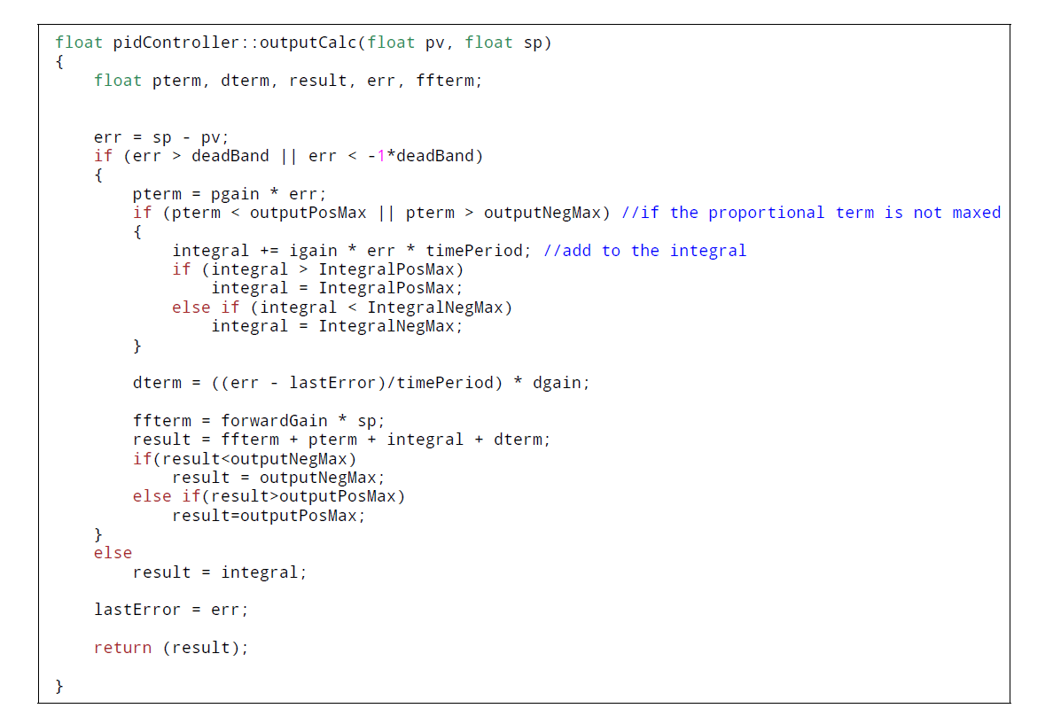
Fig. 4.16 C++ method of the linear feedback controller.
4.4. Parameter Modification and Modes
In addition to a controller set point frame, MYODE also transmits a mode command frame that allows selection of the operating mode, and control mode of each controller. Hence, in the mode frame each MYO-Ganglion has 4 8-bit words (one for each controller) to issue the operating mode commands, and 4 8-bit words to issue the control mode commands. The operating mode commands determine the operation that will be performed using the controller selected in the control mode command.
There are 3 operating mode commands that can be issued: initialise controller, set point update (normal operation mode), and disable controller. The first operating mode indicates to a motor that the controller selected in the control mode command will have its parameters set, and so to expect parameter data in a dynamic frame that communication cycle. The parameters used by the currently implemented PID controller is a total of 84 bytes, so only one controller in the whole assembly may be updated during each communication cycle, due to the small size of the dynamic segment. However, as the communication cycle operates with a 1ms period, initialising one controller each for the maximum number of motors would only take 24ms. The initialisation operation mode is also used to tune the parameters for the selected controller, e.g., in the case of a PID controller the tunable parameters are the PID gains, and the operating frequency, although other parameters such as control limits may also be updated. It is important to note that the initialise controller mode does not change whether or not a controller is enabled; hence, during initialisation of a MYO-robot all controllers needed can be initialised before any are enabled. The set point update mode enables the selected controller and updates the set point to be used in its control loop; if the controller selected has not been initialised or safety limits are exceeded, an error is reported in the dynamic frame, and it is not enabled. Enabled controllers can be disabled using the disable controller mode.
4.4.1. Dynamic Frame Control Parameters
The configuration parameters are transmitted in the following structure
typedef struct
{
  uint32 tag;/*!<Tag to indicate data type when passing the union*/
  sint32 outputPosMax; /*!< maximum control output in the positive direction in counts, max 4000*/
  sint32 outputNegMax; /*!< maximum control output in the negative direction in counts, max -4000*/
  float32 spPosMax;/*<!Positive limit for the set point.*/
  float32 spNegMax;/*<!Negative limit for the set point.*/
  float32 timePeriod;/*!<Time period of each control iteration in microseconds.*/
  float32 radPerEncoderCount; /*!output shaft rotation (in rad) per encoder count */
  float32 polyPar[4]; /*! polynomial fit from displacement (d)  to tendon force (f) f=polyPar[0]+polyPar[1]*d +polyPar[2]*d^2+ +polyPar[3]*d^3+ +polyPar[4]*d^4 */ //mjp-3rd order?
  float32 torqueConstant; /*!motor torque constant in Nm/A */

  parameters_t params; //the PID or RAW controller Paramters

}control_Parameters_t;
Here it is important to note that the first parameter, tag, indicates the controller type the paramters for. Tag is a value from the following enumeration
 typedef enum comsControllerMode
{
  Raw=0,
  Torque,
  Velocity,
  Position,
  Force,
  JointPosition,
  JointVelocity,
  NoControllers//not a usable control mode, but used on the ganglion to set up the array of controllers
}comsControllerMode;
 typedef union
{
  pid_Parameters_t pidParameters;
  //raw_Parameters_t rawParameters;
}parameters_t;
 typedef struct
{
  float32 integral;/*!<Integral of the error*/
  float32 pgain;/*!<Gain of the proportional component*/
  float32 igain;/*!<Gain of the integral component*/
  float32 dgain;/*!<Gain of the differential component*/
  float32 forwardGain; /*!<Gain of  the feed-forward term*/
  float32 deadBand;/*!<Optional deadband threshold for the control response*/
  float32 lastError;/*!<Error in previous time-step, used to calculate the differential component*/
  float32 IntegralPosMax; /*!<Integral positive component maximum*/
  float32 IntegralNegMax; /*!<Integral negative component maximum*/
}pid_Parameters_t;
4.4.2. Caliper Integration
In order to set motor control parameters as well as the controller reference values manually, a GUI for MYODE plugin suite has been created. Based on the QT4 framework, this interface allows the real time display of all process states which are supplied via the FlexRay bus.
The Myorobot plugin (see Fig. 4.17) for Caliper presents the component parts of the embedded control infrastructure as a tree. The robot has a number of ganglions, each with a number of connected muscles (motors in this case), each muscle has a set of control modes which each have a set of parameters. This tree structure is generated based on the robot configuration file generated by the virtual assembly toolbox, and represents the underlying data structures created. To allow easy testing of a Myorobot, the sensor data transmitted via FlexRay from each ganglion is displayed in the Status column in the row of the associated control mode for each connected muscle. Additionally, control reference values or controller parameters may be sent to the Myorobot via FlexRay by entering them in the ‘Setting Value‘ column. Ranges for each value are automatically enforced, and are only sent to the robot when ‘Send Data’ is pressed; selection of the control mode, and whether to enable or disable each motor is performed using the check boxes.
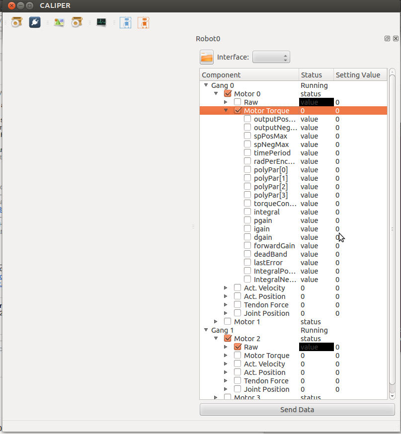
Fig. 4.17 Sceenshot of the Myorobot plugin GUI.
5. Controller Tests
Danger
This control section describes the old MYODE architecture. While most parts of the hardware and firmware are unchanged, the high-level control is very different. The remaining, valid information will be incorporated into the above section.
In this section the basic functionality of the controller infrastructure is demonstrated. The results are not all encompassing and further testing is still ongoing. However, these preliminary results show that the infrastructure in principle is functional, the sensory system is of high quality and linear control of the MYO-Muscles is achievable.
All controller test where carried out by changing the control parameters in the MYODE robot control GUI and then transmitting them via the FlexRay bus to the MYO-Ganglion. The MYO-Ganglion runs the actual linear controllers and communicates with the motor driver in order to read the motor state and set the PWM drive signal.
5.1. Position Motor Control
For the first demonstration of the controller capabilities the position controller running at 100Hz was selected. The demand or reference value was set to 10 rad (shaft position) from an initial position of 0 rad. Fig. 5.2 shows the result with a slightly under-gained PI controller. It is observable that the final position is reached after approximately \(300ms\). During the control phase, the control output saturates at a duty cycle of \(100\%\) and a maximum velocity of approximately \(35 rad/s\) is achieved. Please note that no tendon is attached to the motor and the only ‘load’ is the motor gearbox.
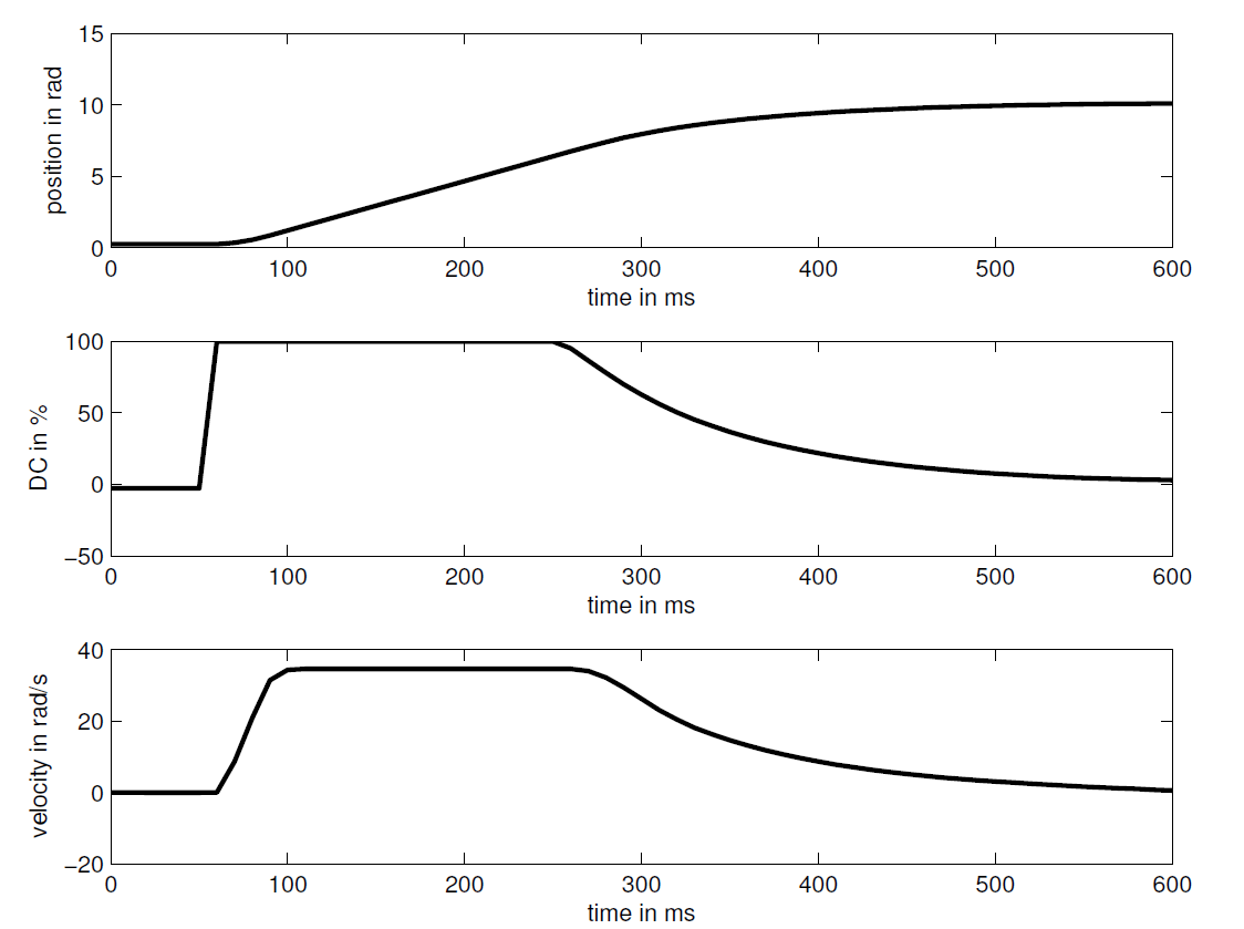
Fig. 5.2 PI control of motor shaft position: motor position in rad (top); duty cycle (DC) of PWM signal (centre); shaft velocity in rad/s (bottom).
In the next experiment (Fig. 5.3), the PI gains were increased and it is observable how the control system overshoots and a slight second-order oscillation is visible.
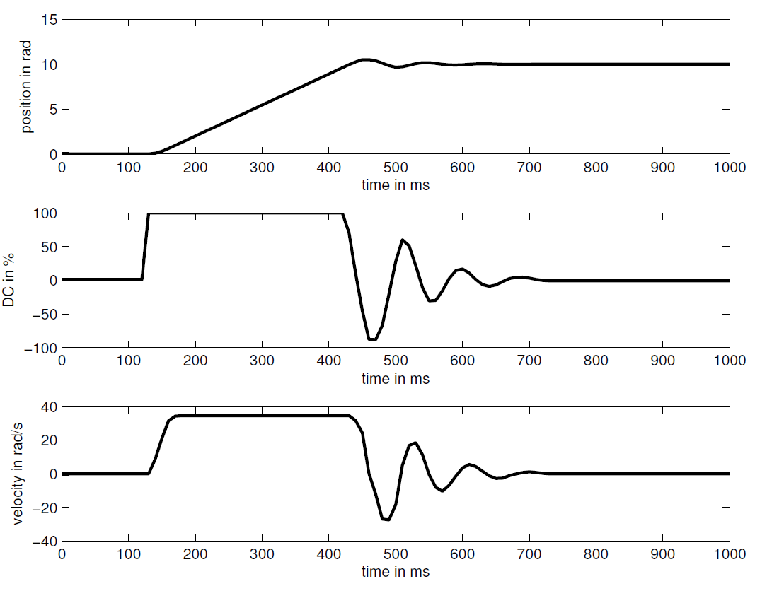
Fig. 5.3 PI control of motor shaft position: motor position in rad (top); duty cycle (DC) of PWM signal (centre); shaft velocity in rad/s (bottom).
In order to reduce this overshoot, the controller is enhanced with a D component and it is clearly visible in Fig. 5.4 that the overshoot is reduced.
Fig. 5.4 PI control of motor shaft position: motor position in rad (top); duty cycle (DC) of PWM signal (centre); shaft velocity in rad/s (bottom).
Overall, this brief set of experiments demonstrates the PID controller’s capabilities and the principle operation. Note, that it was not our intention to tune the system ‘perfectly’ or test all control modes but to merely demonstrate the principle operation of the system. Further tests are required. However, the reader may note the good signal quality and the almost ‘textbook’ plots. All signals shown here are unfiltered and obtained from real experiments.
5.2. Velocity Motor Control
The next set of experiments demonstrate the velocity control mode. Here, a sample rate of \(1KHz\) is chosen and the controller is configured as a PI controller. The step response to a velocity demand is shown in Fig. 5.5 and Fig. 5.6. It is clearly observable how the P element of the controller leads to a very fast increase in shaft velocity and how the I element of the controller then slowly increases the velocity until the reference is reached asymptotically.
Fig. 5.5 PI control of motor shaft velocity:shaft velocity in rad/s (top) ; dutcy cycle (DC) of PWM signal (bottom).
Fig. 5.6 PI control of motor shaft velocity:shaft velocity in rad/s (top) ; dutcy cycle (DC) of PWM signal (bottom).
The velocity signals is obtained by simple numerical differentiation of the encoder signal. The blue line in the plot shows the measured signal and the black line shows the filtered velocity signal (2nd order Butterworth, cut-off frequency 1/5 of Nyquist frequency for the given sample rate). Fig. 5.5 is merely a zoomed in version of Fig. 5.6.
As for the position control, only a small part of the controllers functionality is demonstrated in this summary of work and further tests are ongoing.
5.3. Position Control of 1-DOF Arm
We conclude this page by demonstrating simple position control of the MYO-Muscle with an attached arm. This is a 1-DOF experiment with a single muscle, the counterforce is produced by gravity as can be understood from Fig. 5.7.
Fig. 5.7 Simple Myorobotic test rig: Only the upper MYO-Muscle is attached via the tendon with the distal bone. The experimenter deflects the bone to demonstrate the compliant nature of the system and the sensing capabilities.
In this experiment, the linear feedback controller is configured as a pure P position controller of the MYO-Muscle. To limit the motor velocity and to demonstrate the functionality of the output saturation system, the PWM duty cycle was limited to \(15\%\). The plots in Fig. 5.8 show the joint angle, the motor shaft position and the spring displacement. At \(t \approx 1200 ms\) the motor shaft reference value is changed and it is observable that with the change in motor shaft position the joint angle changes too. The steady state is reached at \(t\approx 2400ms\).
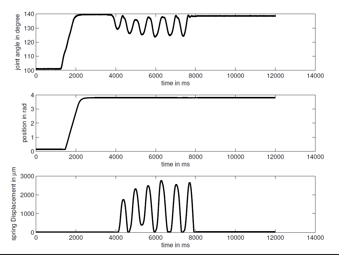
Fig. 5.8 1DOF arm control: the plots show the change of motor, joint and spring position.
It is interesting to note that during the first phase of the motion (from 1200ms to 2400ms) the spring of the MYO-Muscle is not deformed. Only later, at \(t\approx 4000ms\), when the experimenter applies an additional vertical force to the distal bone, is a spring displacement and a change in joint angle observable. What is demonstrated here is the inherent compliance of the musculoskeletal approach. Clearly, under a great load or greater accelerations, a spring displacement is also expected during the change in joint position without external disturbances.
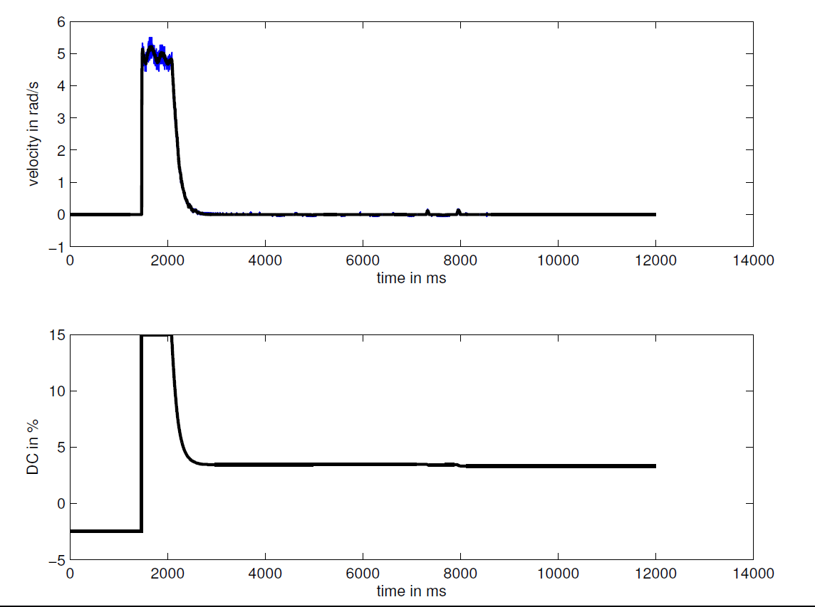
Fig. 5.9 1DOF arm control: the plots show the motor shaft velocity (blue raw signal, black LP filtered) and the duty cycle (DC) of the motor control signal.
Also note that the change in motor shaft position is negligible, i.e. the position controller holds the position despite the external disturbances. In other words, the system is passively compliant and not dependent on ‘softly tuned’ motor controllers.
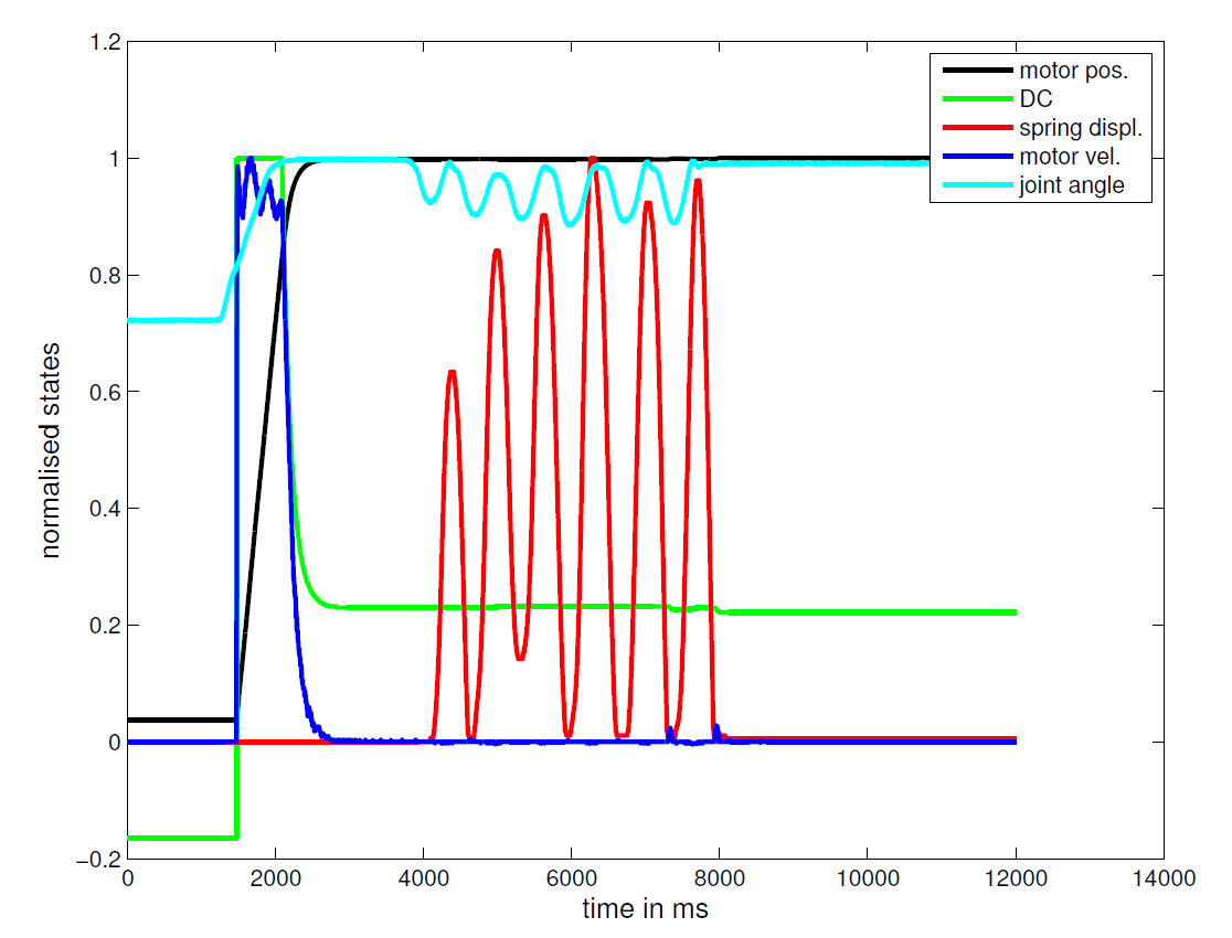
Fig. 5.10 1DOF arm control: normalised plot of MYO-Muscle control states.
To further demonstrate the quality of control system, Fig. 5.10 shows the normalised signals of several motor states. Here it is important to note that the signals are only normalised to allow their display in a single plot in order to demonstrate how they correlate. They are not post-processed for plotting which demonstrate the low-noise nature of our control and signal acquisition system.