3. Content of the design primitive library
3.1. Organization and description of the library elements
To simplify the presentation of the library elements and provide a framework for future extensions, the developed hardware elements are organized, for each DP functional category, using the following hierarchical classification:
Types (T) are used to distinguish the hardware elements on the basis of their design principle.
Varieties (V) are used, if needed, to distinguish the hardware elements based on the same design principles, on the basis of the technical implementation.
The description of each variety follows the following structure:
Illustrations |
regroup figure and graphics illustrating the library element and its main features |
|---|---|
Dimensions |
list the element’s most important dimensions |
Features |
provide a textual explanation of the element’s main features |
Material and fabrication |
detail the materials and fabrication methods foreseen for the various parts of the library element |
Integration of the electronics |
if needed, provides more details about the embedded electronic component and their integration in the hardware element |
Accessories |
lists the additional pieces of hardware usable with the library element, if any |
Implemented instances |
list the instances of the hardware elements that have been implemented so far, with their corresponding names and dimensions |
3.2. Overview of the implemented library elements
3.2.1. Mechanical couplings
3.2.1.1. Structural Bond
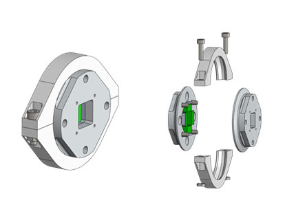
Fig. 3.1 Type 1: Flange clamp with conical flange
3.2.1.2. Anchor Fastener
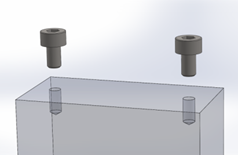
Fig. 3.2 Type 1: Screw Fasteners
3.2.1.3. Cable attachment
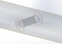
Fig. 3.3 Type 1: Through hole
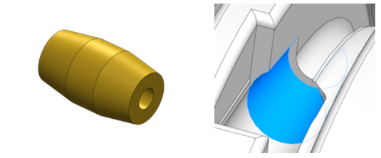
Fig. 3.4 Type 2: Conical socket
3.2.2. Design Primitives
3.2.2.1. MYO-Bones
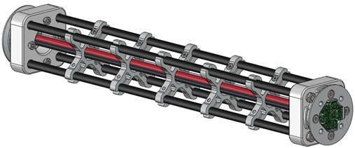
Fig. 3.5 Type 1: Parallel Assemblies - Four Round Tubes Fibres
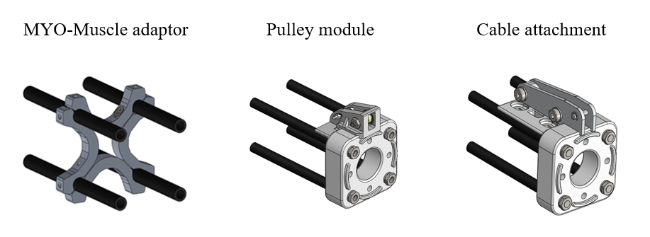
Fig. 3.6 Accessories
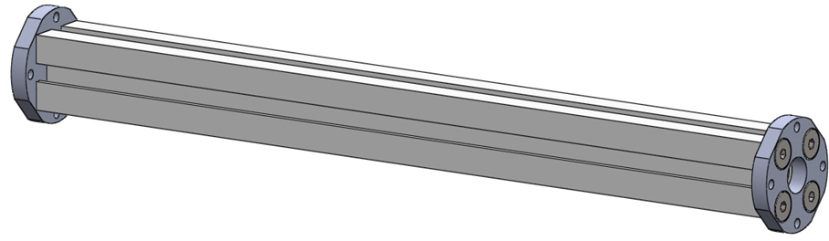
Fig. 3.7 Type 2: Monolithic core - T-slot profile
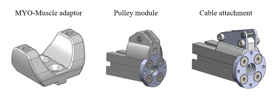
Fig. 3.8 Accessories
3.2.2.2. MYO-Joints
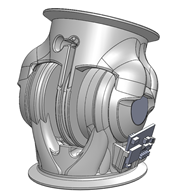
Fig. 3.9 Type 1: Symmetric Hinge
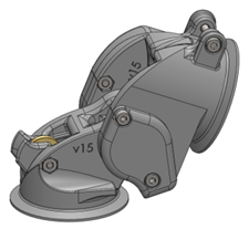
Fig. 3.10 Type 2: Asymmetric Hinge
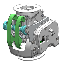
Fig. 3.11 Type 2: Revised Asymmetric Hinge
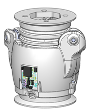
Fig. 3.12 Type 3: Pivot
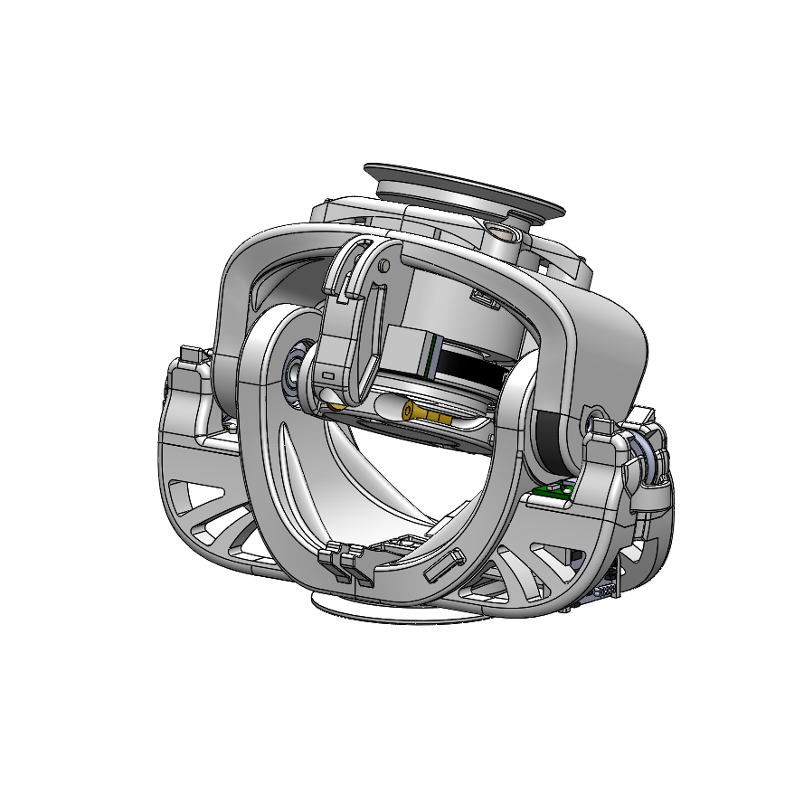
Fig. 3.13 Type 4: Hinge-Pivot
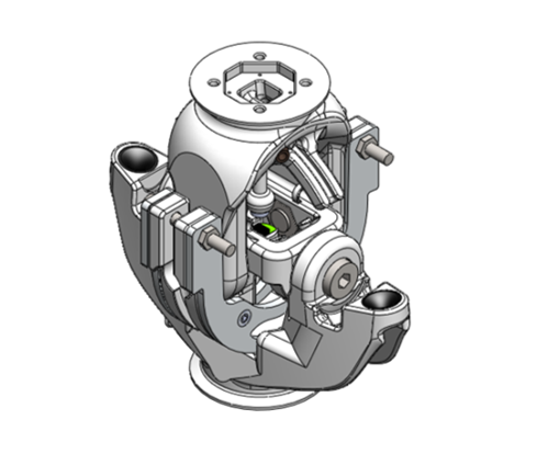
Fig. 3.14 Type 5: Hinge-Hinge
3.2.2.3. MYO-Muscles
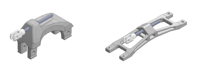
Fig. 3.15 Type 0: Passive Muscle - Simple spring
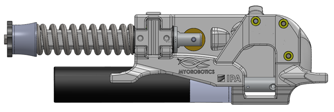
Fig. 3.16 Type 1: Unilateral Series Elastic Actuator - Compression spring
3.2.2.4. MYO-Ganglion
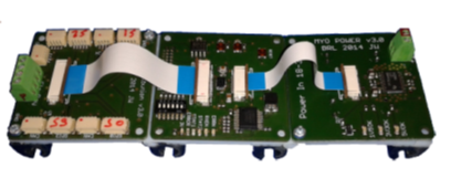
Fig. 3.17 Type 1: ECU with FlexRay bus