9. Motor Driver
In order to drive the MYO-Muscles, a motor driver board is provided. This is illustrated in Fig. 9.1. The motor driver board is supplied with 24V and communicates with the MYO-Ganglion via a 5MHz SPI connection. It provides sockets to connect the MYO-Muscle motor as well as a further connection for the spring-displacement sensor. For further hardware developments and other extensions, there is also a CAN interface and a micro-USB connection. However, they are not required when building a Myorobot.
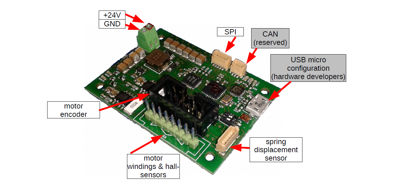
Fig. 9.1 The Myorobotics motor driver board.
9.1. Spring Displacement Sensor
To measure the displacement of the spring (a proxy for tendon force), a spring displacement sensor is connected to the motor driver board. The sensor is supplied via the motor driver board and connected via a 6-pin JST connector [1] as depicted in Fig. 9.2.
9.1.1. Wiring Scheme: Spring Displacement Sensor - Motor Driver Board
This cable is NOT symmetric.
Signal Name |
GND |
EncA |
EncB |
O |
Idx |
+5V |
|---|---|---|---|---|---|---|
Displacement Sensor, pin # |
1 |
2 |
3 |
4 |
5 |
6 |
Motor Driver Board, pin # |
5 |
3 |
2 |
1 |
4 |
6 |
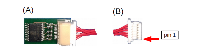
Fig. 9.2 The spring displacement sensor and connector: Please note that the connector cable is not symmetric. Consequently, one end of the connector cable (marked with S or D) is plugged into the sensor board (A) and the other end (B) (marked with M) is plugged into the motor driver board (Fig. 9.1) The connectivity of the cable is described in Section 9.1.1 .
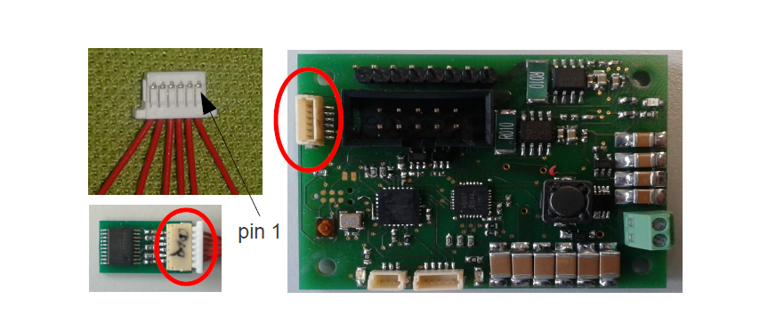
Fig. 9.3 Cables and connectors to connect the spring displacement sensor with the motor driver board; red circles mark the applicable connectors on the printed circuit boards.
9.2. Driver Board Mounting
To illustrate how a motor driver board is mounted on the MYO-Muscle please refer to Fig. 9.4. The connector for the spring displacement sensor should be facing the spring. Two screws are sufficient to mount the motor driver board on the MYO-Muscle as shown in Fig. 9.4.
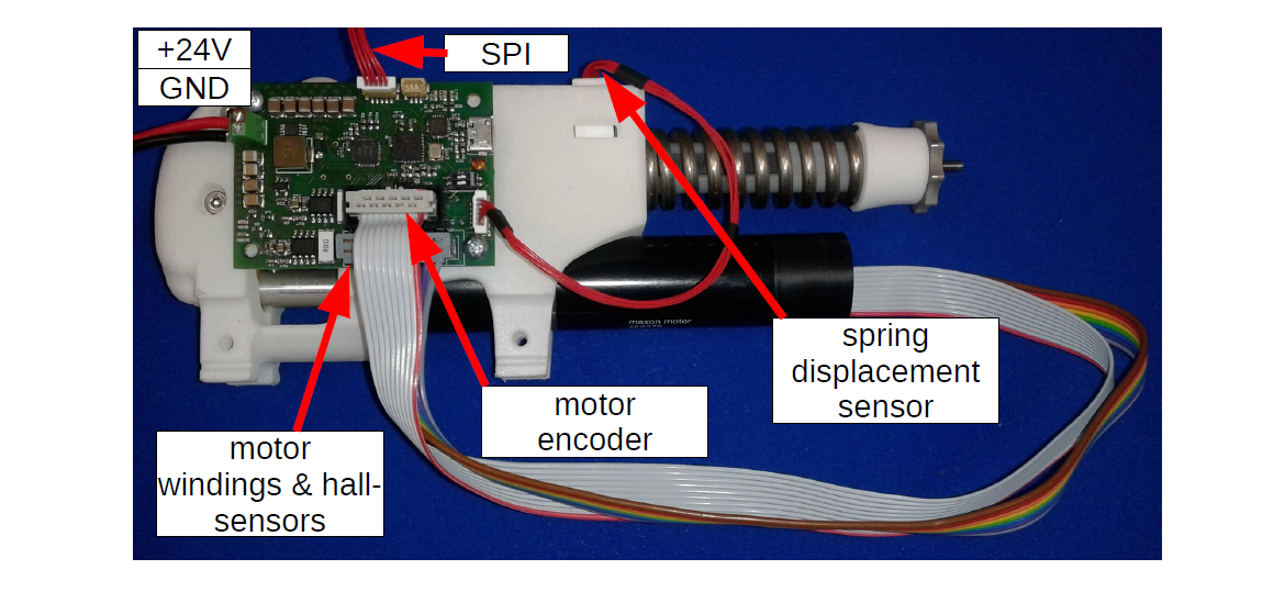
Fig. 9.4 Motor driver board mounted on MYO-Muscle
9.3. Connectivity
The motor driver board has to be connected to the MYO-Ganglion board using the 5-pin JST connectors [2] . Depending where the motor driver board is plugged in (SPI0, SPI1, SPI2 or SPI3) the associate MYO-Muscle can be addressed with the corresponding index the flexrayusbinterface. In other words, the address of a motor driver board (and therefore the MYO-Muscle) is dependent upon the SPI connector it is connected to (see Table 9.1).
SPI Connection |
Address / C++ index |
|---|---|
SPI0 |
[0] |
SPI1 |
[1] |
SPI2 |
[2] |
SPI3 |
[3] |
9.3.1. Wiring Scheme SPI Connector: Ganglion Distribution Board - Motor Driver Board
Signal Name |
SOMI |
SIMO |
Clk |
SS |
Gnd |
|---|---|---|---|---|---|
Ganglion Distribution Board, pin# |
1 |
2 |
3 |
4 |
5 |
Motor Driver Board, pin # |
1 |
2 |
4 |
3 |
5 |
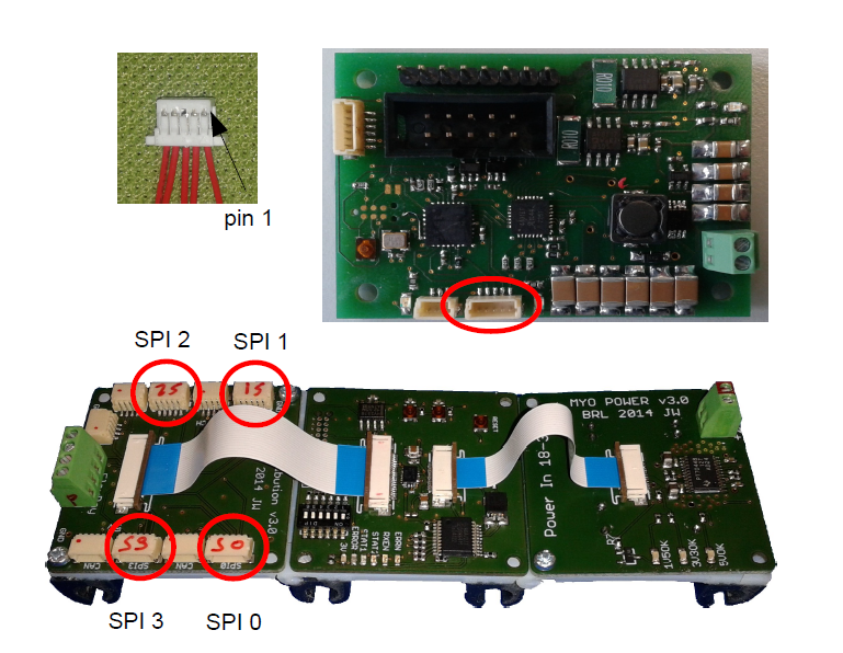
Fig. 9.5 Cables and connectors to connect the SPI of the distribution board with the motor driver board; red circles mark the applicable connectors on the printed circuit boards.