8. Joint Sensor Board
The MYO-Joints are equiped with absolute position sensors. An interface board (joint sensor board) is mounted on each joint as shown in Fig. 8.1. The joint position is sent to the MYO-Ganglion via CAN. The joint sensor board reads the magnetic joint sensor (within the joint) at a rate of 16kHz. A filtered value of this joint position (moving average filter) is sent to the MYO-Ganglion at a rate of 1kHz. Up to 4 joint sensors can be connected to the MYO-Ganglion on a shared CAN bus. The DIP-switches on the joint sensor board are required to configure the CAN message ID (communication address). The DIP switches (S1, S2 and S3) are read after power-on reset. Manipulation of the switches during operation has no effect. For a 1DOF joint DIP switches 1 and 2 are used to set the address (0b00, 0b01, 0b10 or 0b11). Switches 3, 4 and 5 must be in the off position [3]. Switch 6 enables a CAN termination resistor. One (and only one) of the joint sensor boards connected to a MYO-Ganglion must have the termination resistor enabled (i.e. switch 6 ON). In general, CAN requires two \(120\Omega\) termination resistors. One of them is present on the MYO-Ganglion board and therefore only one of the joint sensors should have its termination resistor enabled.
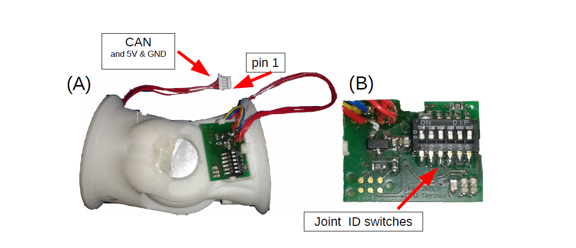
Fig. 8.1 The MYO-Joint (A) with a close-up (B) of the joint angle sensor board
8.1. Connectivity
The joint sensor board is supplied with a 4-pin [4] JST connector and should be directly connected to the MYO-Ganglion using any of the 5 available CAN connectors. The address of the joint is subject to the address of the joint sensor board, using DIP switches 1 and 2 as shown in Table 8.2.
During 1DOF operation, only one CAN message with the MsgID indicated by switches S1 and S2 is sent. For 2DOF operation two CAN messages are sent, the first one has the MsgID indicated by switches S1 and S2, the second CAN message has the ID indicated with switches S1 and S2 plus 1.
S1 |
S2 |
S3 |
messageIDs on bus |
|---|---|---|---|
0 |
0 |
0 |
0x50 |
0 |
0 |
1 |
0x50 and 0x51 |
0 |
1 |
0 |
0x51 |
0 |
1 |
1 |
0x51 and 0x52 |
1 |
0 |
0 |
0x52 |
1 |
0 |
1 |
0x52 and 0x53 |
1 |
1 |
0 |
0x53 |
1 |
1 |
1 |
0x53 |
S1 |
S2 |
Address / C++ index |
|---|---|---|
0 |
0 |
[0] |
0 |
1 |
[1] |
1 |
0 |
[2] |
1 |
1 |
[3] |
8.1.1. Wiring Scheme: Joint Angle Sensor Board - Ganglion Distribution Board
Signal Name |
CAN-H |
CAN-L |
Gnd |
+5V |
|---|---|---|---|---|
Sensor board, pad # |
1 |
2 |
3 |
4 |
Ganglion Distribution Board, pin # |
3 |
2 |
1 |
4 |
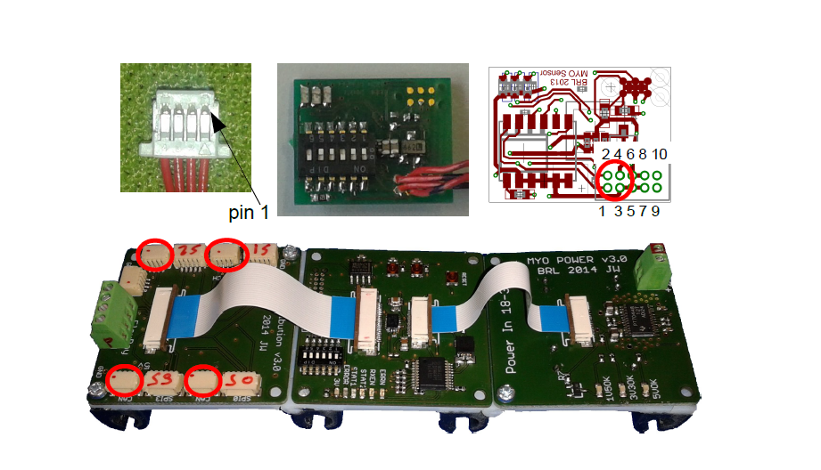
Fig. 8.2 Cables and connectors to connect the joint angle sensor board to the ganglion distribution board; red circles mark the applicable connectors on the printed circuit boards.
8.1.2. Wiring Scheme: Analogue joint sensor - Joint Angle Sensor Board
The analogue joint sensor are soldered straight into the soldering pad on the joint angle sensor boards. The joint angle sensor board can output 5V or 3.3V on pins 6 and 8, depending on the components configured onto the joint angle sensor board.
Signal Name |
Gnd |
Gnd |
+5V/3.3V |
+5V/3.3V |
AN0 |
AN1 |
|---|---|---|---|---|---|---|
Sensor board, pad # |
5 |
7 |
6 |
8 |
9 |
10 |
8.1.3. Wiring Scheme: 5V and 3.3V configuration
The joint angle sensor board can operate with 5V or 3.3V sensors, depending on the resistors populated and solder-bridges made. Details can be seen in Fig. 8.3. Resistors R5,R6,R7 and R8 are required to divide down the sensor output, in case of the 5V configuration, to the 3.3 analogue input voltage range of the micro-controller on the sensor board. One, and only one, solder-bridge (SB) between the 5V pad or 3.3V pad and the \(V_{supply}\) pad is required to supply the sensor with the appropriate voltage. For 3.3V operations resistors R7 and R8 should be removed and R5 and R6 replaced with a 0\(\Omega\) resistor.
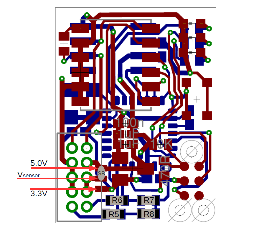
Fig. 8.3 PCB with components for 5V operation: \(R5=5k\Omega,R6=5k\Omega,R7=10k\Omega,R8=10k\Omega\) and solder-bridge (SB) implementing the connection between +5V and the sensor supply voltage \(V_{sensor}\). For 3.3V operation the solder-bridge is required between the 3.3V pad and \(V_{senosr}\). Importantly, the SB between +5V and \(V_{sensor}\) needs then be removed. In 3.3V operation R7 and R8 should be removed and R5 and R6 replaced with a \(0\Omega\) resistor (or a resistance \(<10\Omega\)). Red tracks/pads mark the PCB top, blue tracks/pads are on the bottom side of the PCB.
8.2. Calibration Procedure
The joints should be calibrated before the first operation. This makes sure that the digital outputs of the sensor board map symmetrically to the physical range of the analogue sensors. A calibrated sensor will broadcast a value of \(2048_{dec}\) in the centre position and a value between 0 and \(2048_{dec}\) at the physical negative end-stop (depending on range). The value at the positive end-stop will be between \(2048_{dec}\) and \(4095_{dec}\), again depending on the physical range. The calibration only needs to be performed once when connecting the sensor board to the physical joint and sensor, the calibration data is stored permanently in the flash memory of the joint angle sensor board. However, the procedure can be repeated if mistakes were made during calibration or if he sensor board is mounted onto another joint. The calibration data is agnostic to the to the joint address in principle. However, it is easiest to perform the calibration when joint ID zero (S0=0, S1=2) is selected. The calibration works for 1DOF and 2DOF operation. The following procedure will lead to a successful calibration:
S0 and S1 are set to 0 (off), S4 is off, S3 off in 1DOF operation or S3 on for 2DOF operation
power up joint angle sensor board
set S4 to on
move joint to negative position, hold there
flick S0 on and off again
move joint to positive position, hold there
flick S1 on and off again
set S4 to off
calibration has been performed