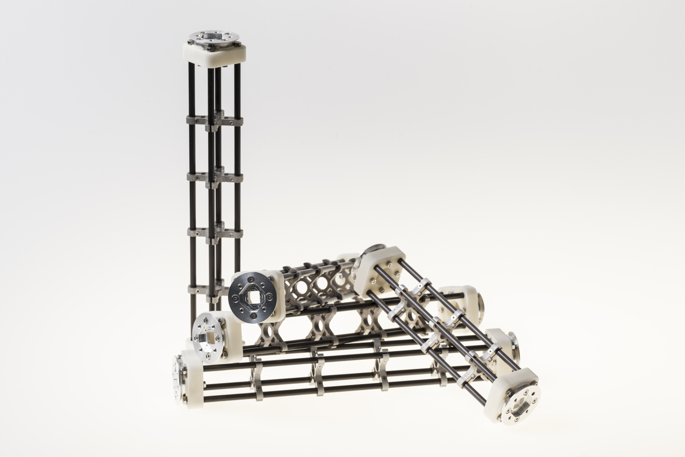
2.1. MyoBone ‘Parallel Assemblies’ - Four Round Tube Fibres
2.1.1. Prepare parts
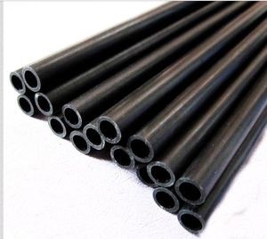
2.1.1.1. Step 1: Cut fibres to the desired length
Tips:
Lathe can create a precise cut and avoids damaging the tube
2.1.1.2. Step 2: Mill the tube ends
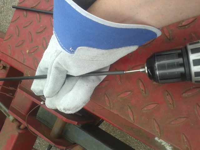
Mill the inside hole of both tube ends in order to create a rough surface for gluing.
Tips:
Use a round moulding cutter with an automatic screwdriver
Use gloves to protect you from dust
2.1.1.3. Step 3: Positioning of the tube length
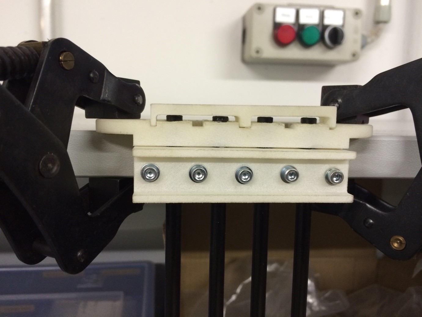
Insert the tubes in the tube holding-support and position the tubes with the distance support. Fix the tubes with the screws.
2.1.1.4. Step 4: Gluing threaded pin in tube ends
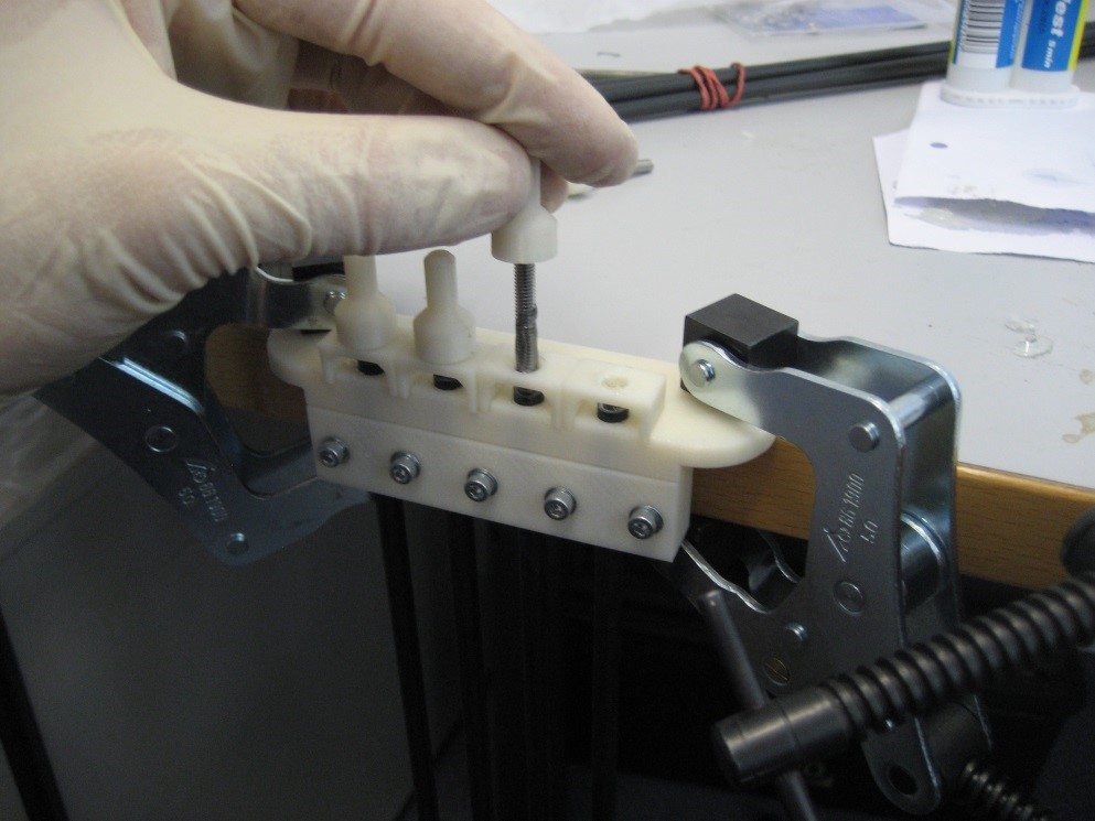
Add glue evenly to the threaded pin and hole. Use the distances according to the MYO-Bone class.
Tips:
While drying, use a fixture to keep the thread pin and fibre centred and at the correct distance
Wear protective gloves
2.1.1.5. Step 5: Remove the leftover glue
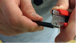
Remove the glue with a cutter knife. Consider the hardening-time of the glue.
Production of spacers
2.1.1.6. Step 1: Water-jet
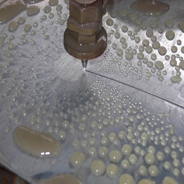
Order water-jet cut part shape (aluminium).
2.1.1.7. Step 2: Drilling and threading of holes
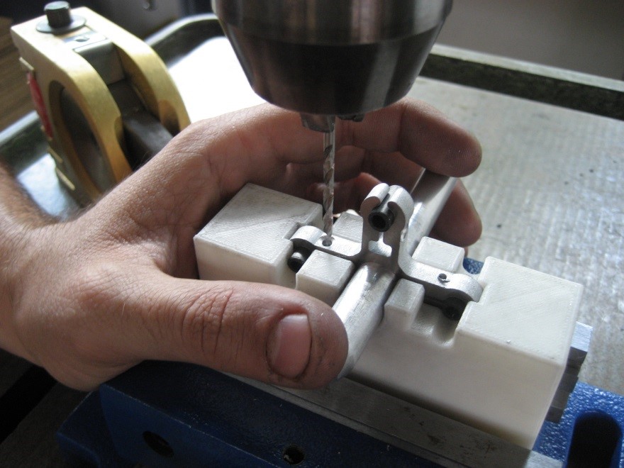
Drill and thread the holes of the flexure clamps.
Tips:
Put small fibers in the flexure clamps to avoid deformation caused by the pressure exerted by the drill bit
2.1.1.8. Production of end plates and flanges
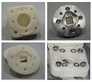
End Spacer:
Selective Laser Sintering (Polyamide)
SB Flange plate:
Machining (Aluminium)
Selective Laser Sintering (Polyamide)
Screws, nuts and washers are standard parts.
2.1.2. Assembly
Material needed
4 x CFRP tubes with threaded ends
4 x spacers
16 x M2.5x10 countersunk head screw (DIN 965)
2 x end spacer
8 x M4 thin nut (DIN 39)
8 x M4 spring washer (DIN 127)
2 x SB flange plates
8 x M3x25 countersunk head screw (DIN 7991)
8 x M3 thin nut (DIN 39)
8 x M3 spring washer (DIN 6798)
2.1.2.1. Step 1: Assemble fibres and spacers
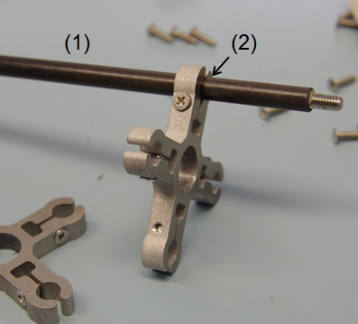
Slide the fibres (1) in the flexure clamps (2) of the spacers.
Tips:
Slide one fibre through all spacers, and then go on with the next fibre
Flexure clamp screws should be loose
In preparation for the next step, regroup the spacers next to each other
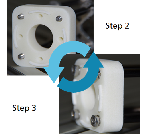
2.1.2.2. Step 2: Plug fibres in the end-spacer
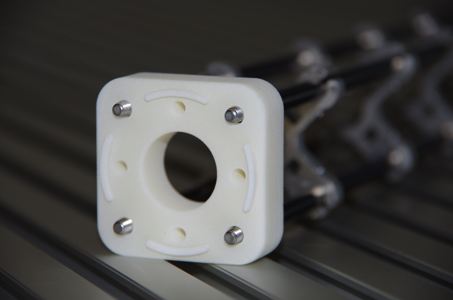
Plug each fibre in one of the holes of the end-spacer.
Tips:
Apply sufficient pressure so that the end of the cfc tube is in contact with the shoulder at the bottom of the hole
Do not press the fibers firmly into the holes
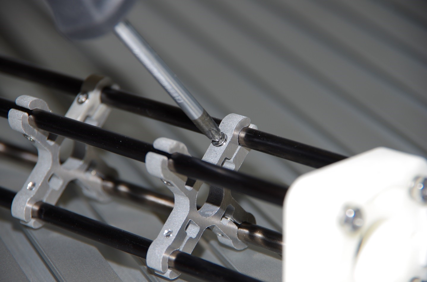
2.1.2.3. Step 3: Screw fibres to the end spacer
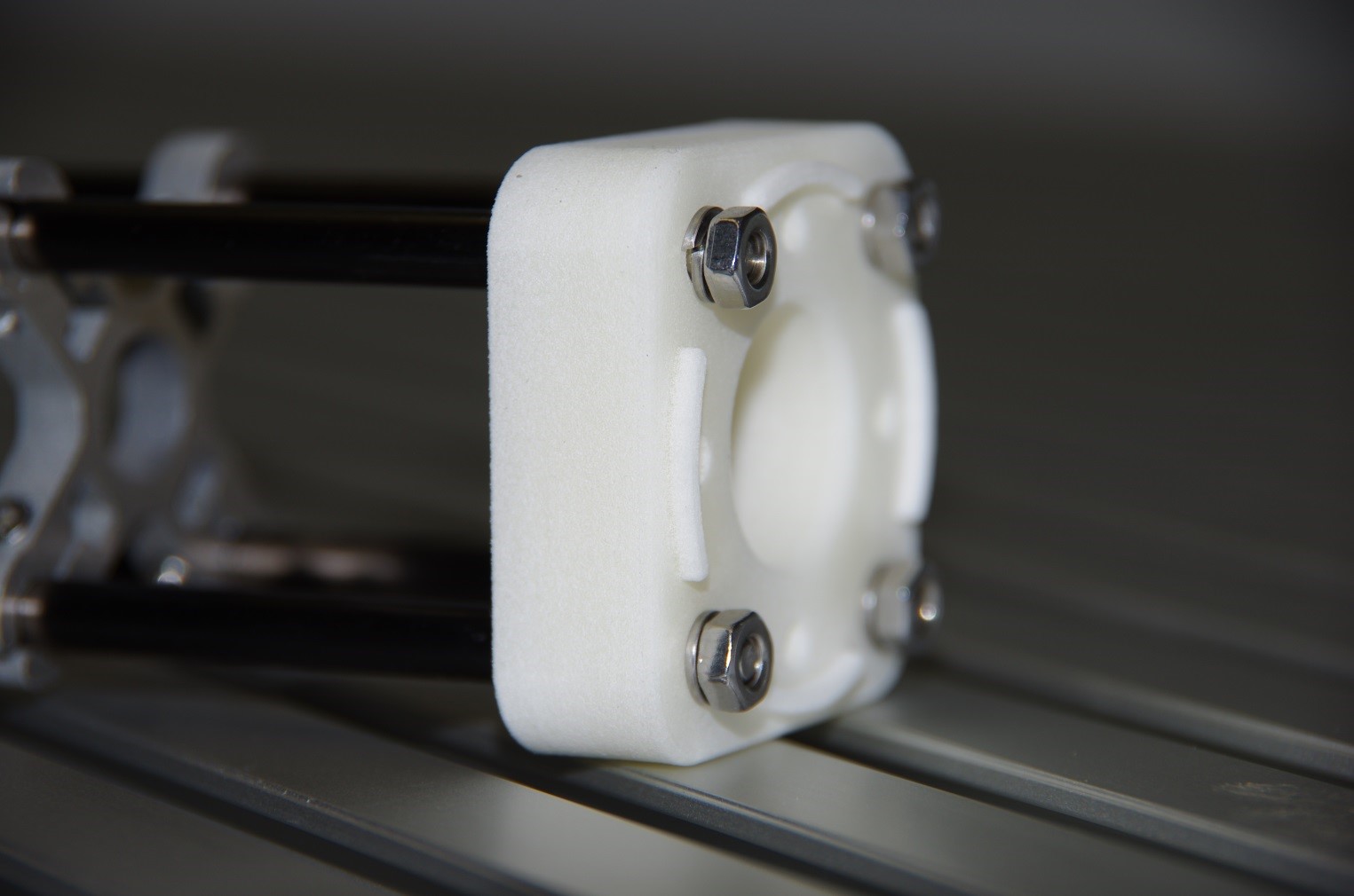
Screw each of the fibers to the end-spacer using the M4 nuts and the large spring washers.
Tips:
Screw the nut until the spring washer is nearly flat, not more
(if you screw further, you may pull the threaded pin out of the tube)
2.1.2.4. Step 4: Attach the other end-spacer
Repeat steps 2 & 3 for the other end-spacer.
Tips:
Make sure the end-spacers are as much as possible:
Parallel to each other
Perpendicular to the fibres
Lay the bone on the table to ensure that it is not twisted
2.1.2.5. Step 5: Adjust the spacers
Arrange the spacers equidistantly between the two end-spacers.
Tips:
Distance between spacers: 51 to 52 mm
Ensure that the spacers are perpendicular to the fibres
2.1.2.6. Step 6: Check straightness
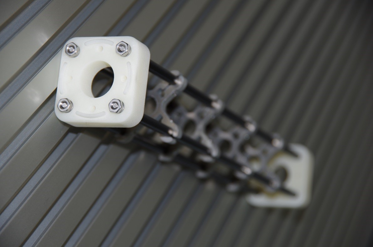
Check that the MYO-Bone is straight and that both end-spacers are parallel to each other.
If necessary proceed to adjustments.
2.1.2.7. Step 7: Attach the SB flange plates
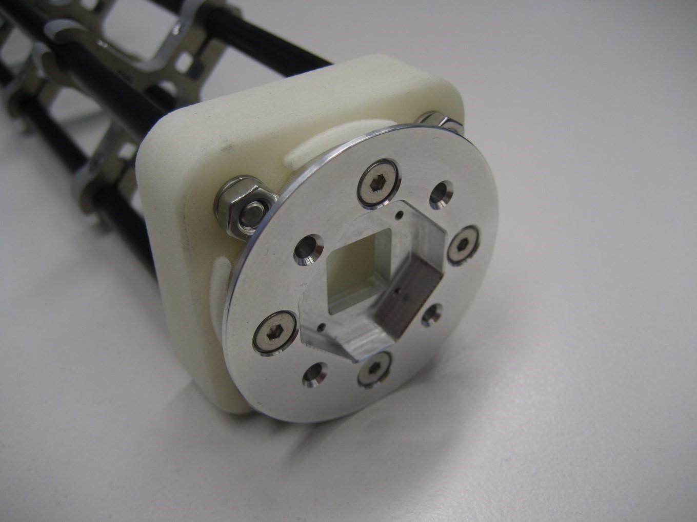
Screw the SB flange plates to the end-spacers with the M3 screws.
Use the small spring washers together with the M3 nuts (backside).