3.1. J22 Symmetric Joint
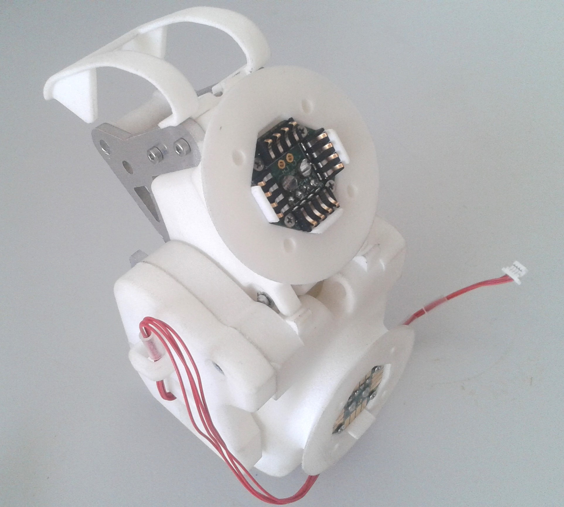
Fig. 3.18 Fully assembled J22 asymmetric joint showing the optional connectivity in the flange.
3.1.1. Parts List
The parts list is maintained at roboy.open-aligni.com.
External users can access it using the following credentials:
user: roboy
password: roboy
Level |
Manufacturer P/N |
Manufacturer Name |
Part Type |
Description |
Quantity |
Designator |
|---|---|---|---|---|---|---|
0 |
J22 Asymmetric joint |
MyoRobotics Consortium |
Joints |
Asymmetric elbow joint |
1 |
|
1 |
J22 prox joint end |
GI |
MyoCAD |
Under joint fork that provides an interface for the structural bond. |
1 |
|
1 |
J22 dist joint end |
GI |
MyoCAD |
Upper joint fork that provides an interface for the structural bond. |
1 |
|
1 |
J22 prox lever arm adapter |
GI |
Machined parts |
2 |
||
1 |
J22 dist level arm adapter |
GI |
Machined parts |
2 |
||
1 |
J22 axle assembled |
GI |
MyoCAD |
This is all the parts required to make the axle pin work in the asymmetric joint |
1 |
|
2 |
J22 axle |
GI |
Machined parts |
This is the joint axle that goes through the upper and under joint fork |
1 |
|
2 |
626-2Z |
NKE |
Bearings |
Bearing 6 x 19 x 6 mm |
2 |
|
2 |
1950-007 |
Wegertseder GmbH - Schrauben Shop |
Nuts, rings, inserts |
Circlip 9 x 1mm |
2 |
|
2 |
1950-004 |
Wegertseder GmbH - Schrauben Shop |
Nuts, rings, inserts |
Circlip 6 x 0.7 |
2 |
|
2 |
MyoArm Assembly |
GI |
Labour |
0.17 |
||
1 |
J22 cover |
GI |
MyoCAD |
Side cover of the joint for myorobotics elbow asymmetric |
1 |
|
1 |
J22 cover sensor |
GI |
MyoCAD |
This covers the magnet and the SIM board |
1 |
|
1 |
J22 cabel cover v4 |
GI |
MyoCAD |
This used in the asymmetric joint to decrease the risk of the cable jumping out the guiding pulley. |
1 |
|
1 |
J22 Guiding pulley assembled |
MyoRobotics Consortium |
Accessories |
Putting together of the small guided pully |
1 |
|
2 |
J22 pulley centre |
GI |
MyoCAD |
Is used to create the pulley which is then inserted in to the upper joint fork |
1 |
|
2 |
693-2Z |
NKE |
Bearings |
Bearing 3 x 8 x 4 mm |
1 |
|
2 |
1018-066 |
Wegertseder GmbH - Schrauben Shop |
Screws, Bolts and Rods |
Zylinderstift 3x8 |
1 |
|
2 |
MyoMuscle Assembly |
GI |
Labour |
0.17 |
||
1 |
J22 Cabel centering |
GI |
MyoCAD |
This used in the asymmetric joint to decrease the risk of the cable jumping out the guiding pulley. |
1 |
|
1 |
Large Hinge Pin 6x45 |
MyoRobotics Consortium |
Screws, Bolts and Rods |
The labour to create the groves and attach the washer |
1 |
|
2 |
1018-190 |
Wegertseder GmbH - Schrauben Shop |
Screws, Bolts and Rods |
Hinge pin 45 x 6 mm |
1 |
|
2 |
MyoArm Assembly |
GI |
Labour |
0.17 |
||
2 |
1956-114 |
Wegertseder GmbH - Schrauben Shop |
Nuts, rings, inserts |
Lock washer 5 mm |
2 |
|
1 |
Large Hinge Pin 4x25 |
MyoRobotics Consortium |
Screws, Bolts and Rods |
1 |
||
2 |
1018-112 |
Wegertseder GmbH - Schrauben Shop |
Screws, Bolts and Rods |
cylindric bolt 25 x 4 mm |
1 |
|
2 |
MyoArm Assembly |
GI |
Labour |
0.17 |
||
2 |
1956-110 |
Wegertseder GmbH - Schrauben Shop |
Nuts, rings, inserts |
Lock washer 3.2 mm |
2 |
|
1 |
Large Hinge Pin 3x24 |
MyoRobotics Consortium |
Screws, Bolts and Rods |
This is the labour need to create the hinge pin groves and attach washers (was meant to be 3x25) |
1 |
|
2 |
1018-082 |
Wegertseder GmbH - Schrauben Shop |
Screws, Bolts and Rods |
Zylinderstift 3x24 |
1 |
|
2 |
1956-108 |
Wegertseder GmbH - Schrauben Shop |
Nuts, rings, inserts |
Lock washer 2.3 mm |
2 |
|
2 |
MyoArm Assembly |
GI |
Labour |
0.17 |
||
1 |
1956-108 |
Wegertseder GmbH - Schrauben Shop |
Nuts, rings, inserts |
Lock washer 2.3 mm |
2 |
|
1 |
1956-114 |
Wegertseder GmbH - Schrauben Shop |
Nuts, rings, inserts |
Lock washer 5 mm |
2 |
|
1 |
1956-110 |
Wegertseder GmbH - Schrauben Shop |
Nuts, rings, inserts |
Lock washer 3.2 mm |
2 |
|
1 |
812 000 020.800 |
Kerb Konus |
Nuts, rings, inserts |
Brass Insert M2 |
5 |
|
1 |
813 000 030.800 |
Kerb Konus |
Nuts, rings, inserts |
Brass Insert M3 |
4 |
|
1 |
852 000 030.800 |
Kerb Konus |
Nuts, rings, inserts |
Brass Insert M3 |
4 |
|
1 |
J22 pulley prox joint end |
GI |
MyoCAD |
This is used for the pulley for the cable to be able to move |
1 |
|
1 |
MyoJoint Sensor |
GI |
MyoRobotics Products |
Joint sensor for a MyoRobotics elbow |
1 |
|
2 |
Joint Angle Sensor Board (JASB) |
Embedded Robotic Systems LLP |
Microcontroller |
Sim board used with the magnet in the asymmetric joint |
1 |
|
2 |
RMM44A3A00 |
RLS |
Microcontroller |
Magnet for the sensor board |
1 |
|
2 |
Cable JASG to CAN |
GI |
Tendon, Rope, Cables |
CAN bus cable for the joint sensor |
1 |
|
3 |
SH3-SH3-28300 |
JST |
Tendon, Rope, Cables |
Cable, crimped, 300mm for JST SH series |
4 |
|
3 |
SHR-04V-S-B |
JST |
Tendon, Rope, Cables |
|
1 |
|
3 |
MyoMuscle Assembly |
GI |
Labour |
0.15 |
||
3 |
SPUL/1.2/3.2MMBLK SPUL/1.2/3.2MMBLK |
Pro Power |
Tendon, Rope, Cables |
Shrink Tube 3.2-1.2mm |
0.1 |
|
2 |
Cable magnetic joint sensor to JASB |
GI |
Tendon, Rope, Cables |
Wires that come out of the joint |
1 |
|
3 |
MyoMuscle Assembly |
GI |
Labour |
0.75 |
||
3 |
2842/19 RD005 |
Alpha Wire |
Tendon, Rope, Cables |
Redwire for magnet ( 30.5m, Diameter 0.688mm) |
10 |
|
3 |
2842/19 BL005 |
Alpha Wire |
Tendon, Rope, Cables |
Blue wire for magnet ( 30.5m, Diameter 0.688mm) |
10 |
|
3 |
2842/19 GR005 |
Alpha Wire |
Tendon, Rope, Cables |
Green wire for magnet ( 30.5m, Diameter 0.688mm) |
10 |
|
2 |
RMB20VA10BC1 |
RLS |
Sensors |
Magnet sensor board |
1 |
|
1 |
2534-278 |
Wegertseder GmbH - Schrauben Shop |
Screws, Bolts and Rods |
M3 screw cylinder 8mm into the lower joint fork |
8 |
|
1 |
2534-234 |
Wegertseder GmbH - Schrauben Shop |
Screws, Bolts and Rods |
M2 screw cylinder 6mm |
5 |
|
1 |
J22 prox lever arm adapter bonnet |
GI |
MyoCAD |
2 |
3.1.2. Upper Joint Fork
3.1.2.1. Step 1: Mount metal sheets on upper joint fork
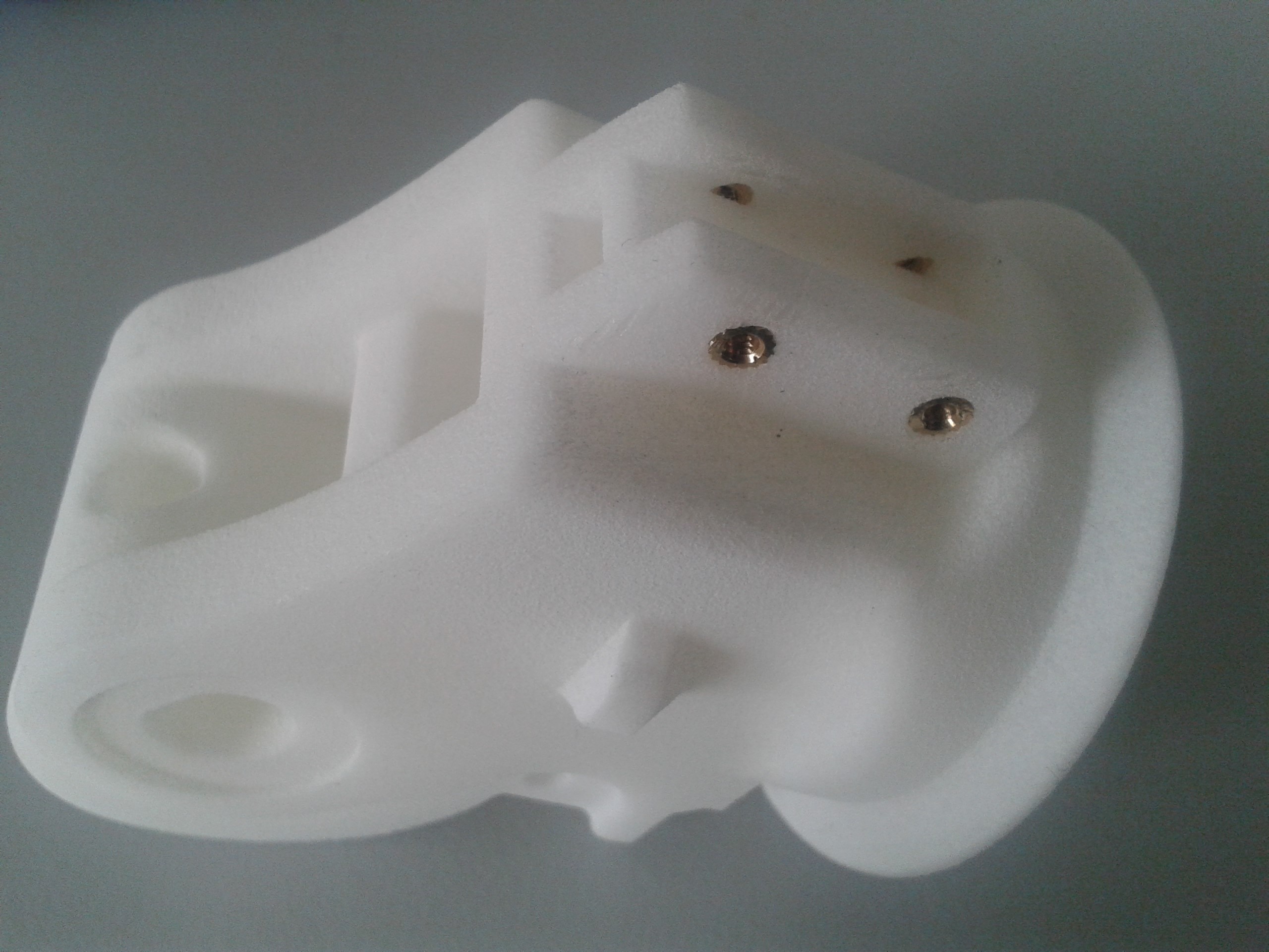
Fig. 3.19 Press the four M2 brass inserts into the upper joint fork using pliers or a bench vise.
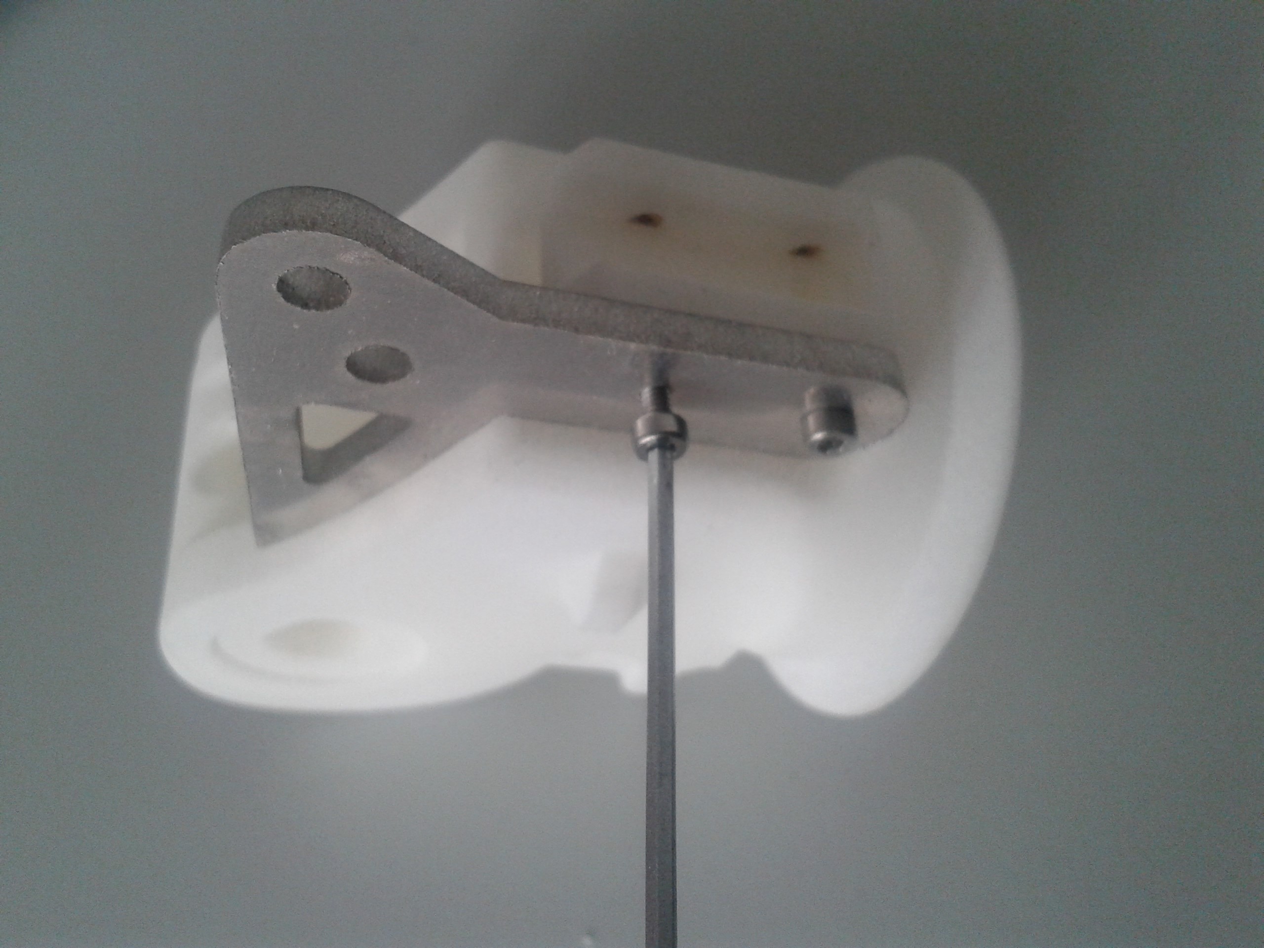
Fig. 3.20 Screw the two upper metal sheets on the sides with M2 screws.
3.1.2.2. Step 2: Mount the cable catching
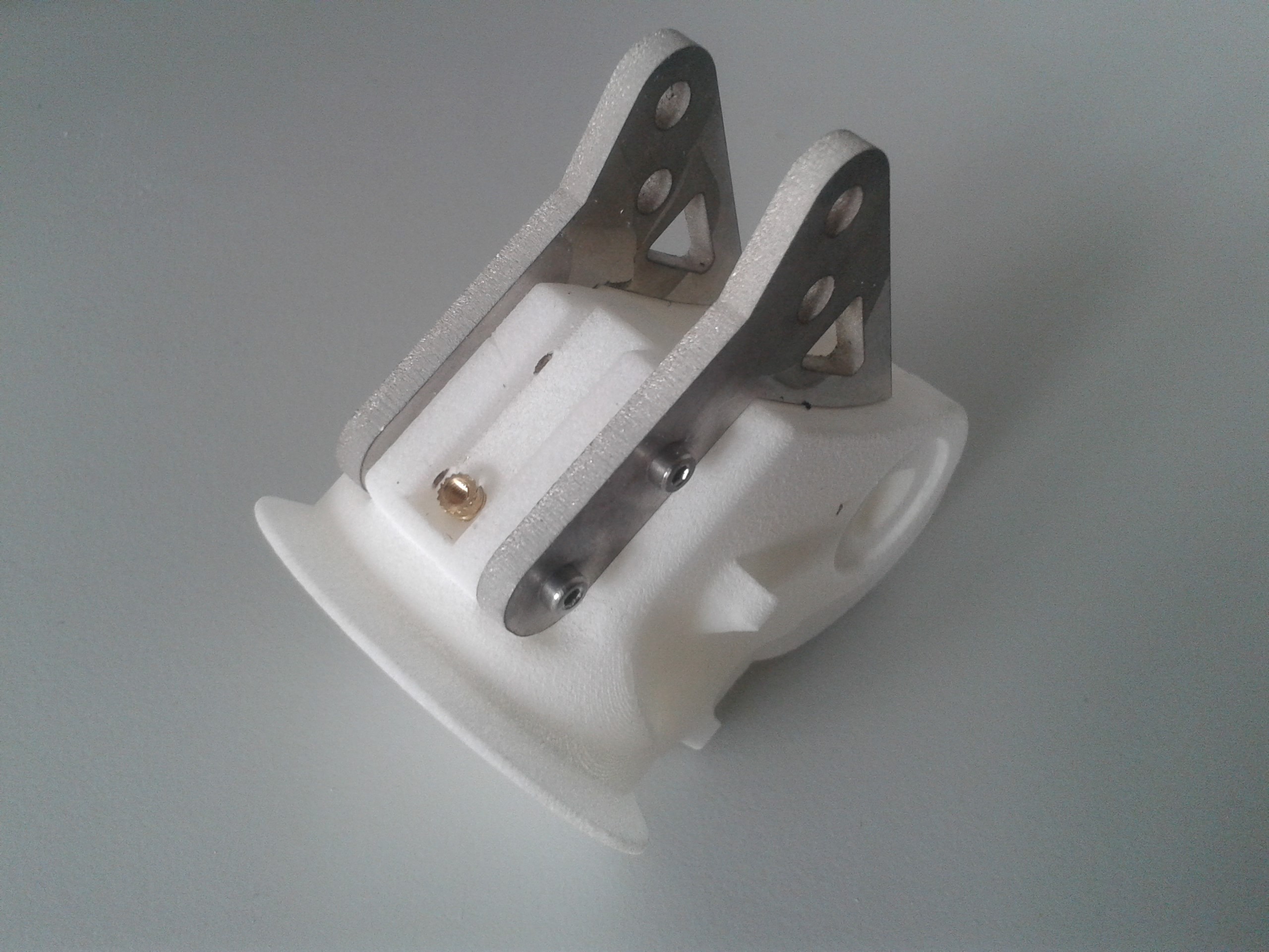
Fig. 3.21 Press the M2 brass insert into the upper joint fork on the top side.
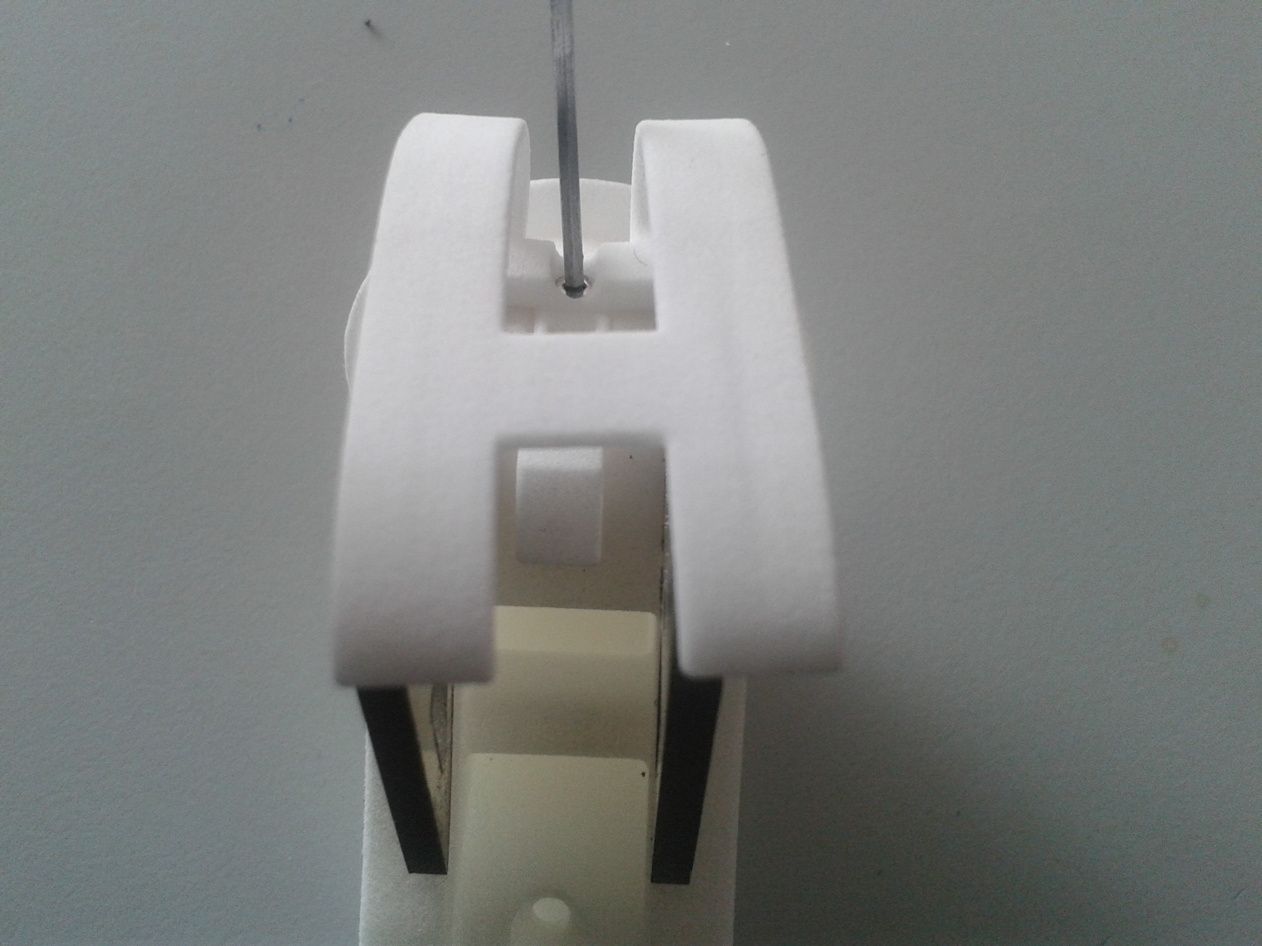
Fig. 3.22 Fix the cable catching mechanism with M2 screws.
3.1.2.3. Step 3: Mount the guiding pulley
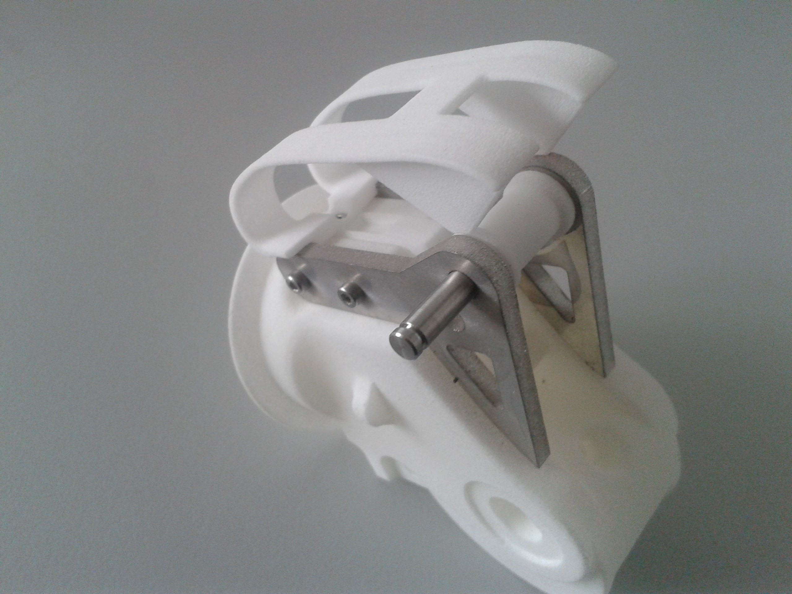
Fig. 3.23 Place the pulley between the metal sheets. Push in the pulley axle (hinge pin 25x4 mm).
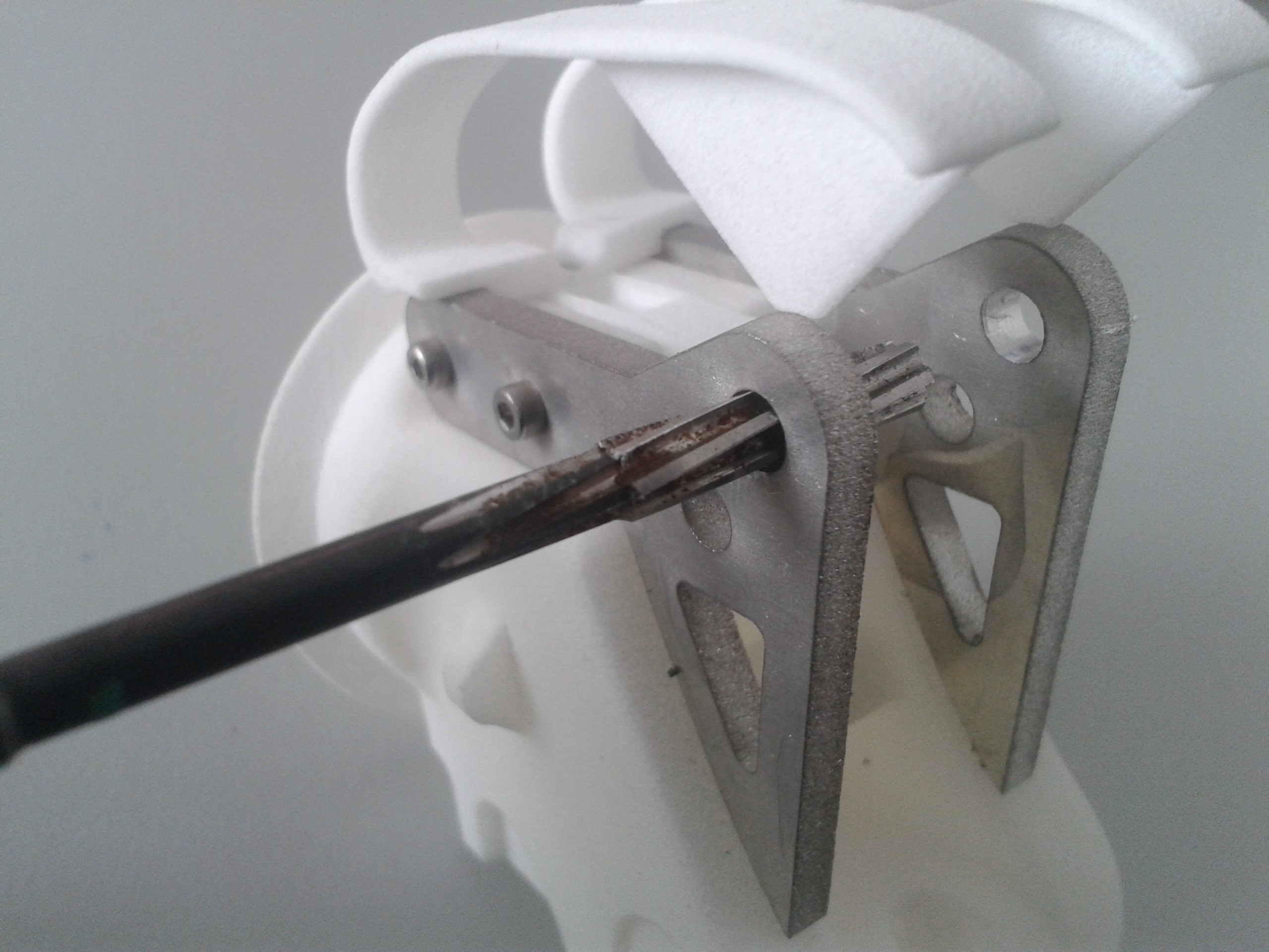
Fig. 3.24 If needed adjust the diameter of the holes of the metal sheets.
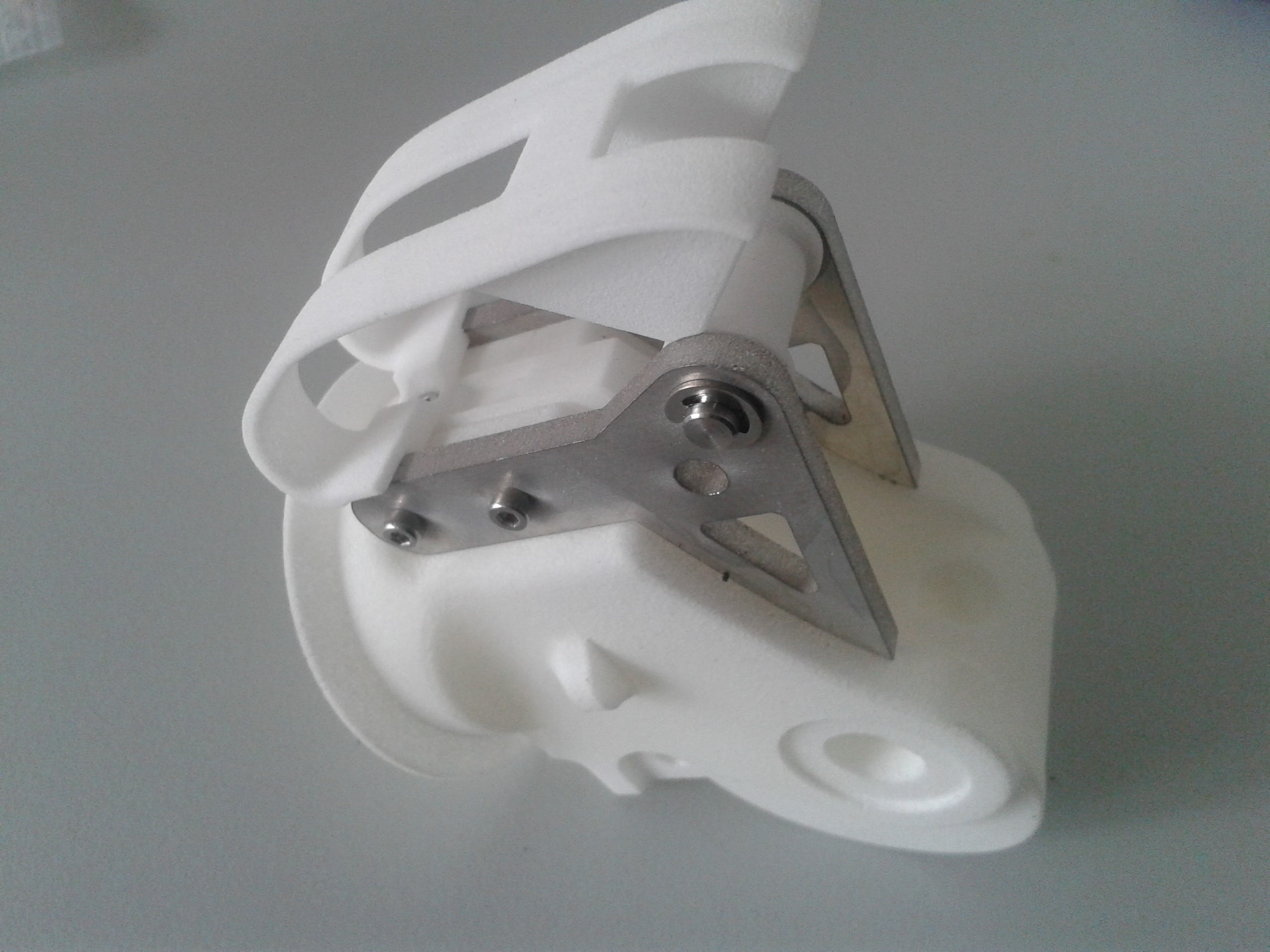
Fig. 3.25 Secure the axle on both sides with lock washers or locktite.
3.1.3. Lower Joint Fork
3.1.3.1. Step 4: Mount the metal sheets on the under joint fork
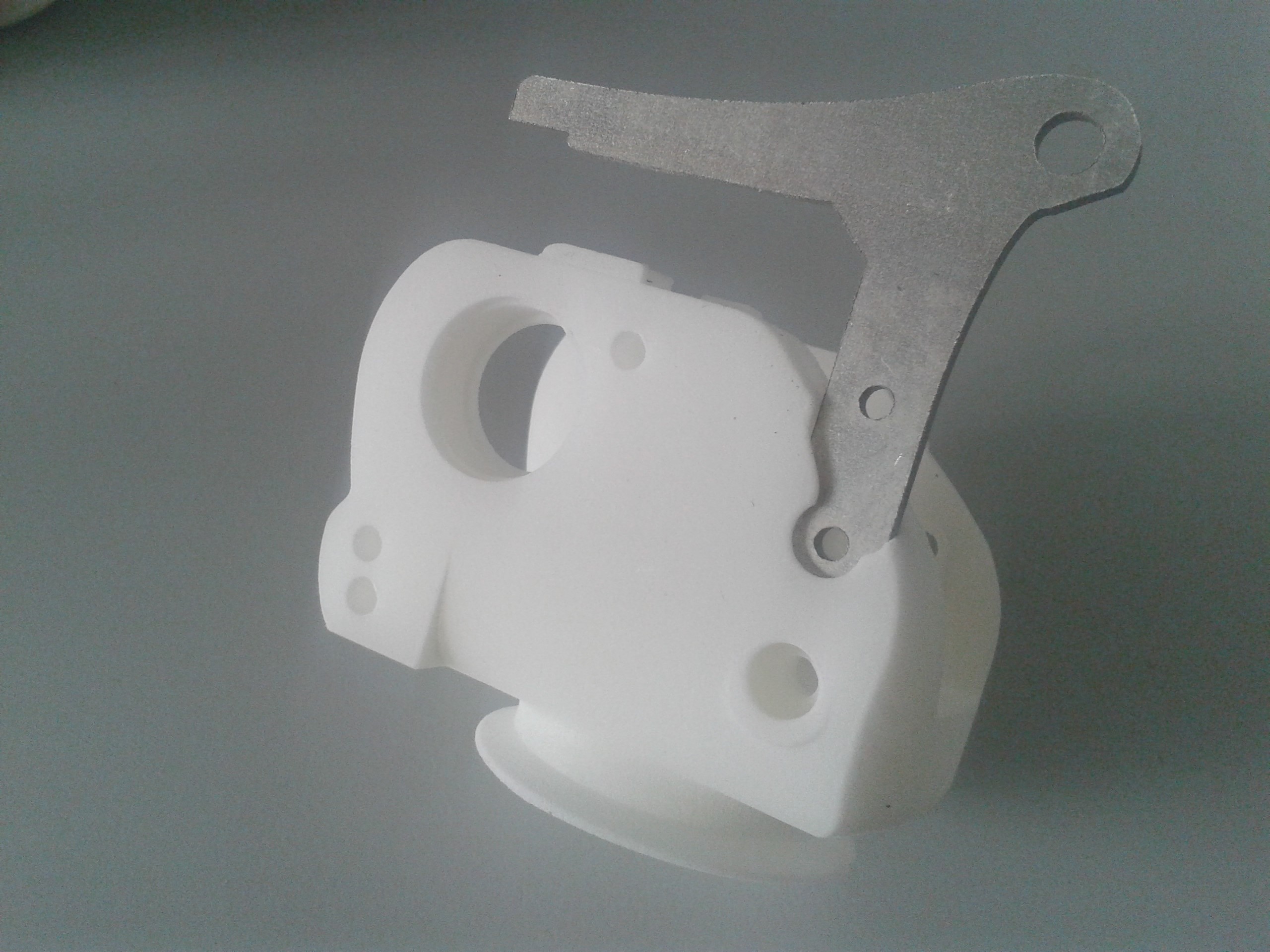
Fig. 3.26 Insert the M3 brass inserts (with heads) in the holes on the inside of the joint, and the M3 brass inserts (without heads) from the outer side.
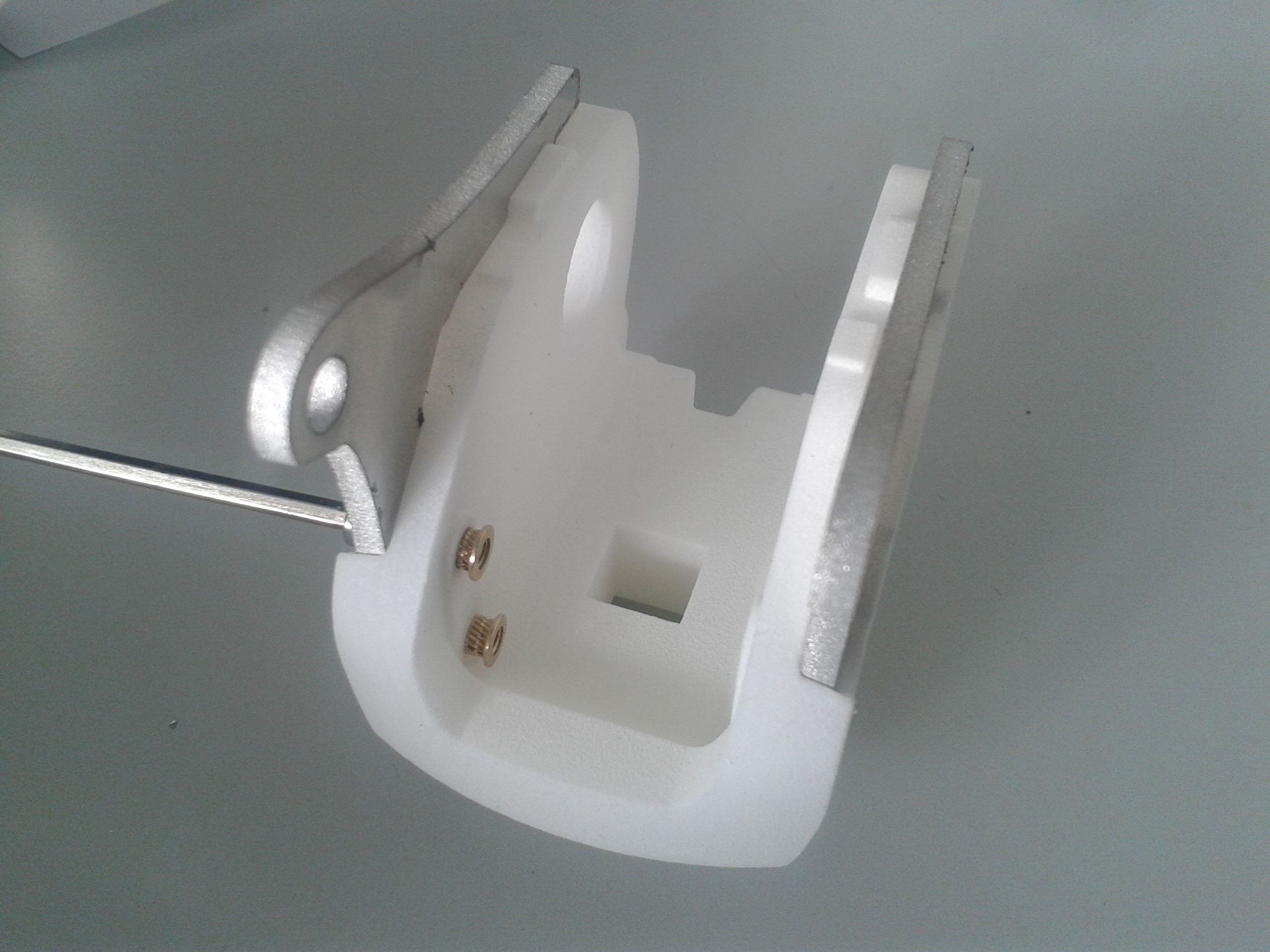
Fig. 3.27 Insert the under metal sheets in the appropriate slots and fix them with M3 screws
3.1.3.2. Step 5: Mount the cable fixation pin
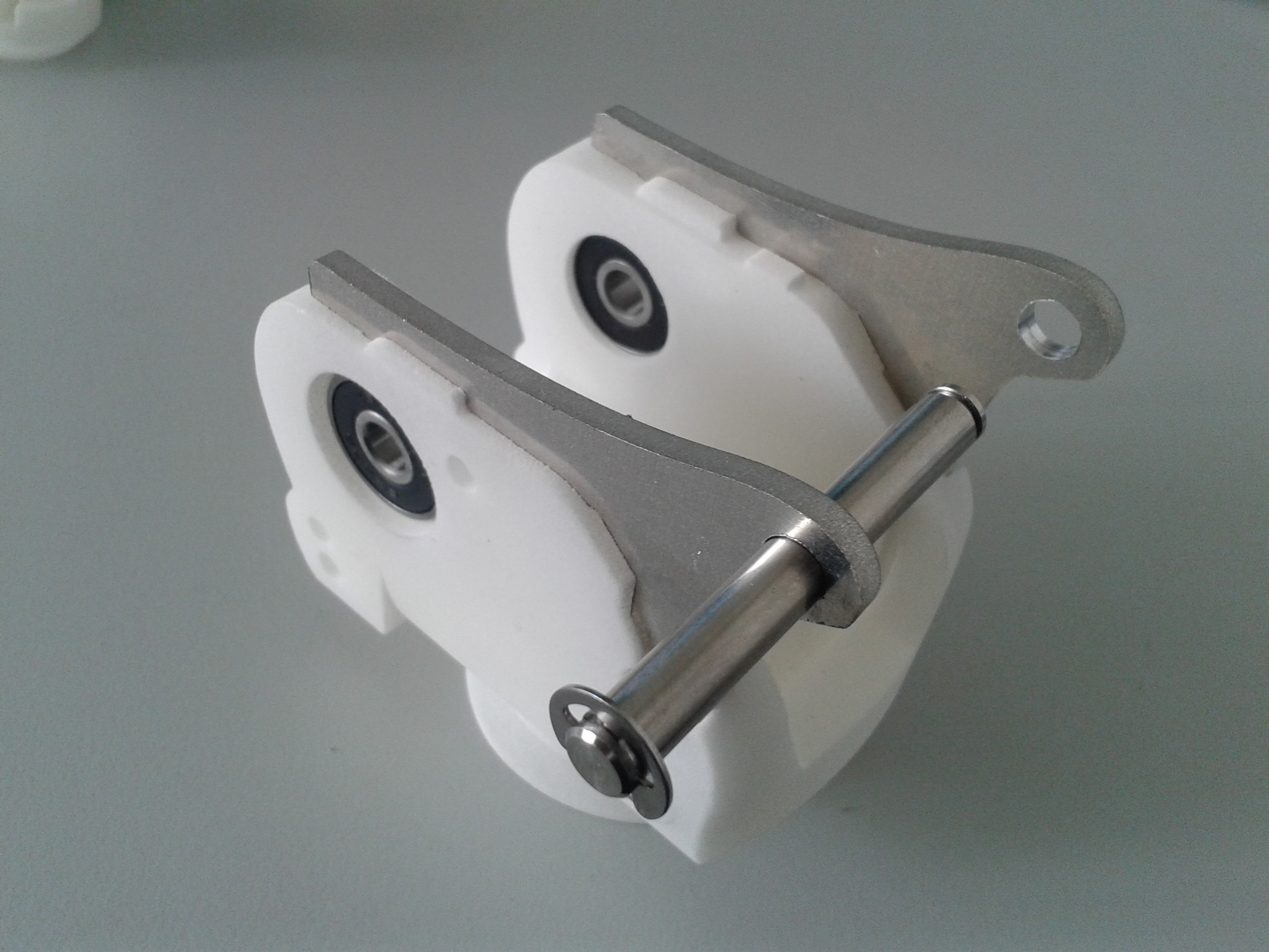
Fig. 3.28 Mount the cable fixation pin
(if needed) adjust the diameter of the mounting holes for pin (hinge pin 45x6 mm)
Mount the pin
Secure the pin on both sides with the lock washers
Clip on it the cable centring clip or glue in the pin
Note: Bearings should not be in the under joint fork at this time
3.1.3.3. Step 6: Mount the guiding pulley
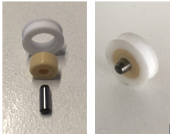
Fig. 3.29 Press the ball bearing into the pulley. Insert the axle pin in the ball bearing
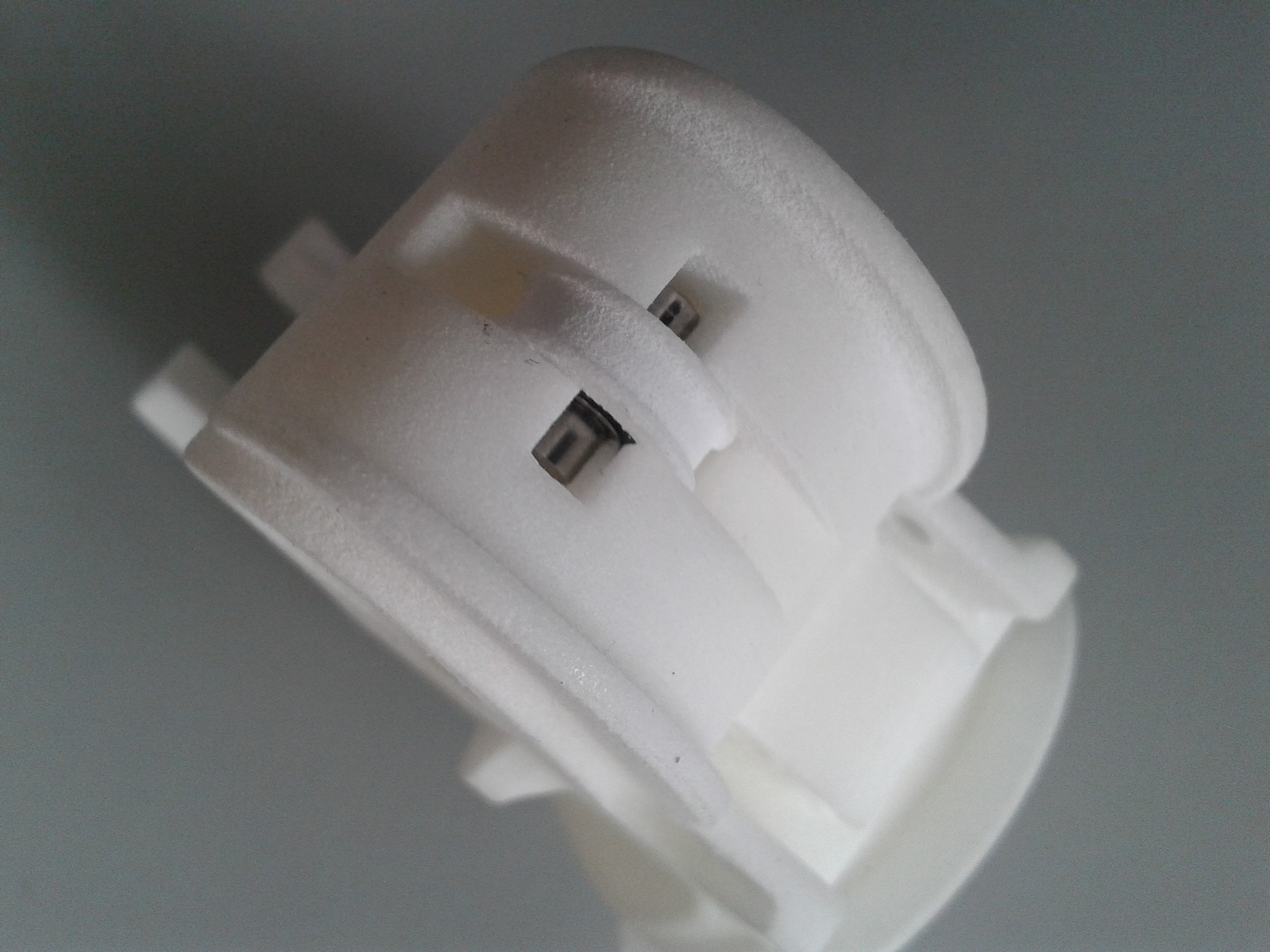
Fig. 3.30 Mount the assembly in to the upper joint fork
3.1.3.4. Step 7: Assemble the joint axle (part 1)
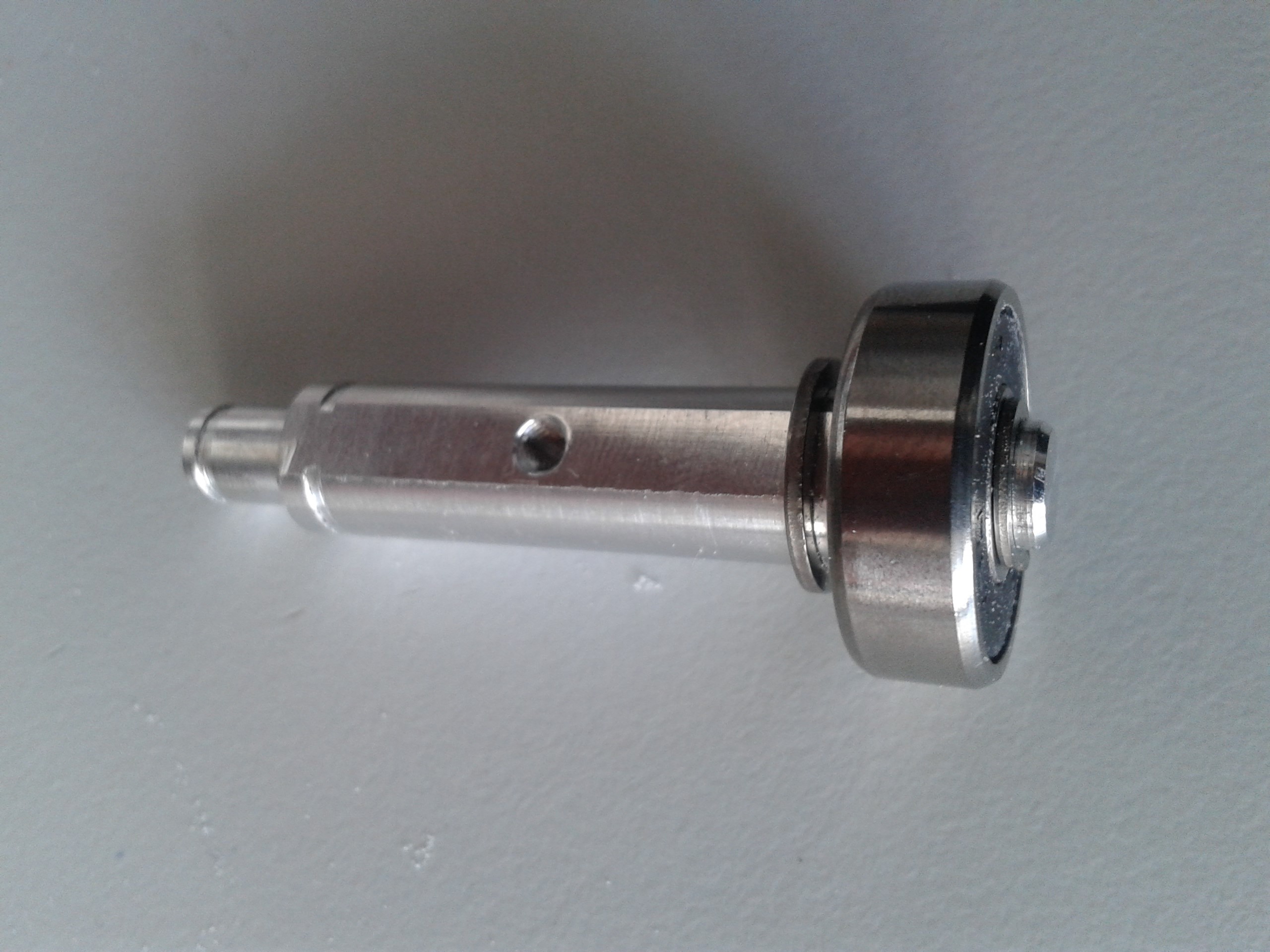
Fig. 3.31 Mount joint axle side.
Mount on one side of the joint axle: - one of the large circlips (DIN 471 - 9 x 1) - one ball bearing - one of the small circlips (DIN 471 -6 x 0.7)
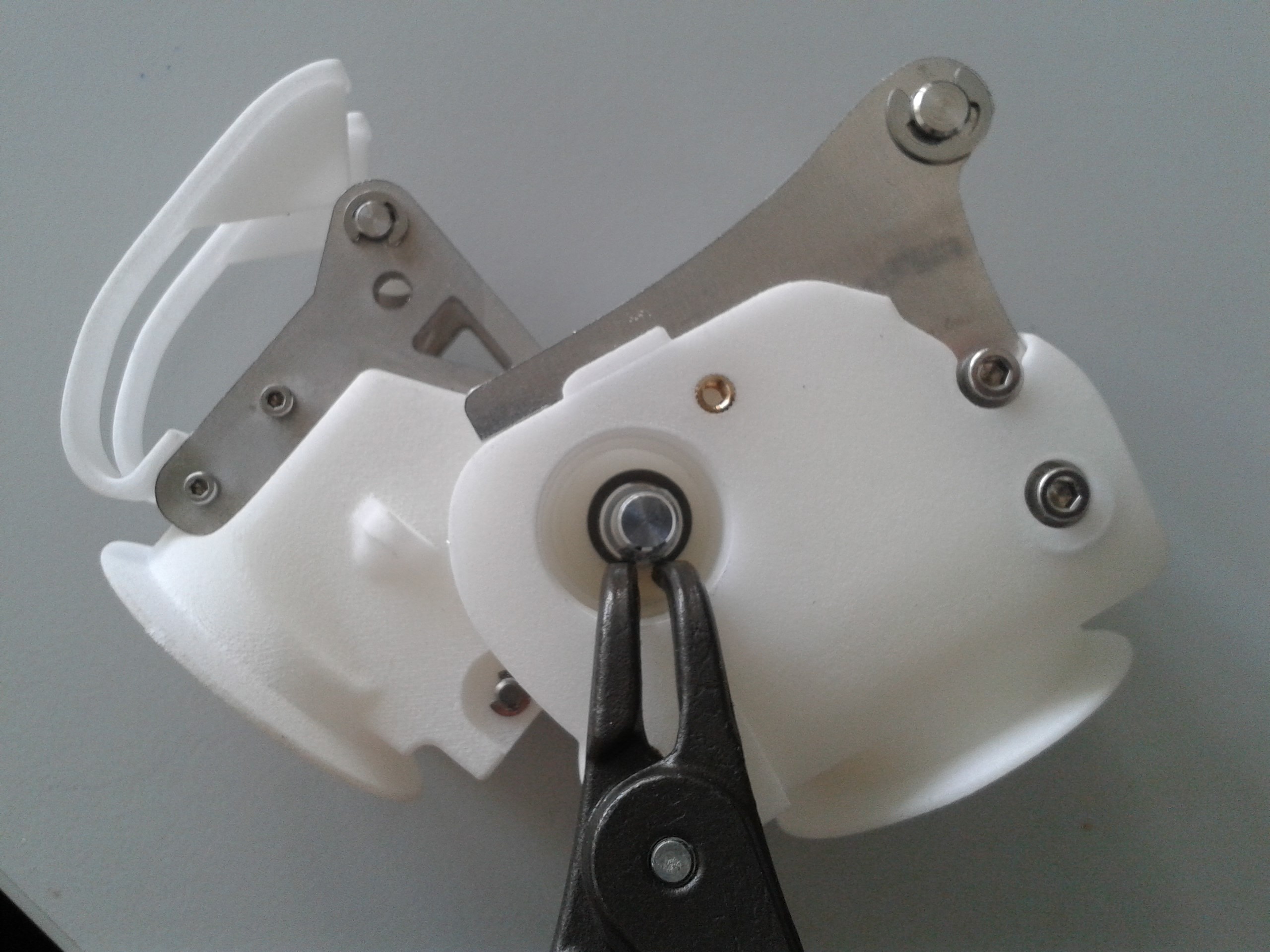
Fig. 3.32 Insert the joint axle through the upper and under joint forks. Mount the other large circlip on the other side of the joint axle
3.1.3.5. Step 8: Assemble the joint axle (part 2)
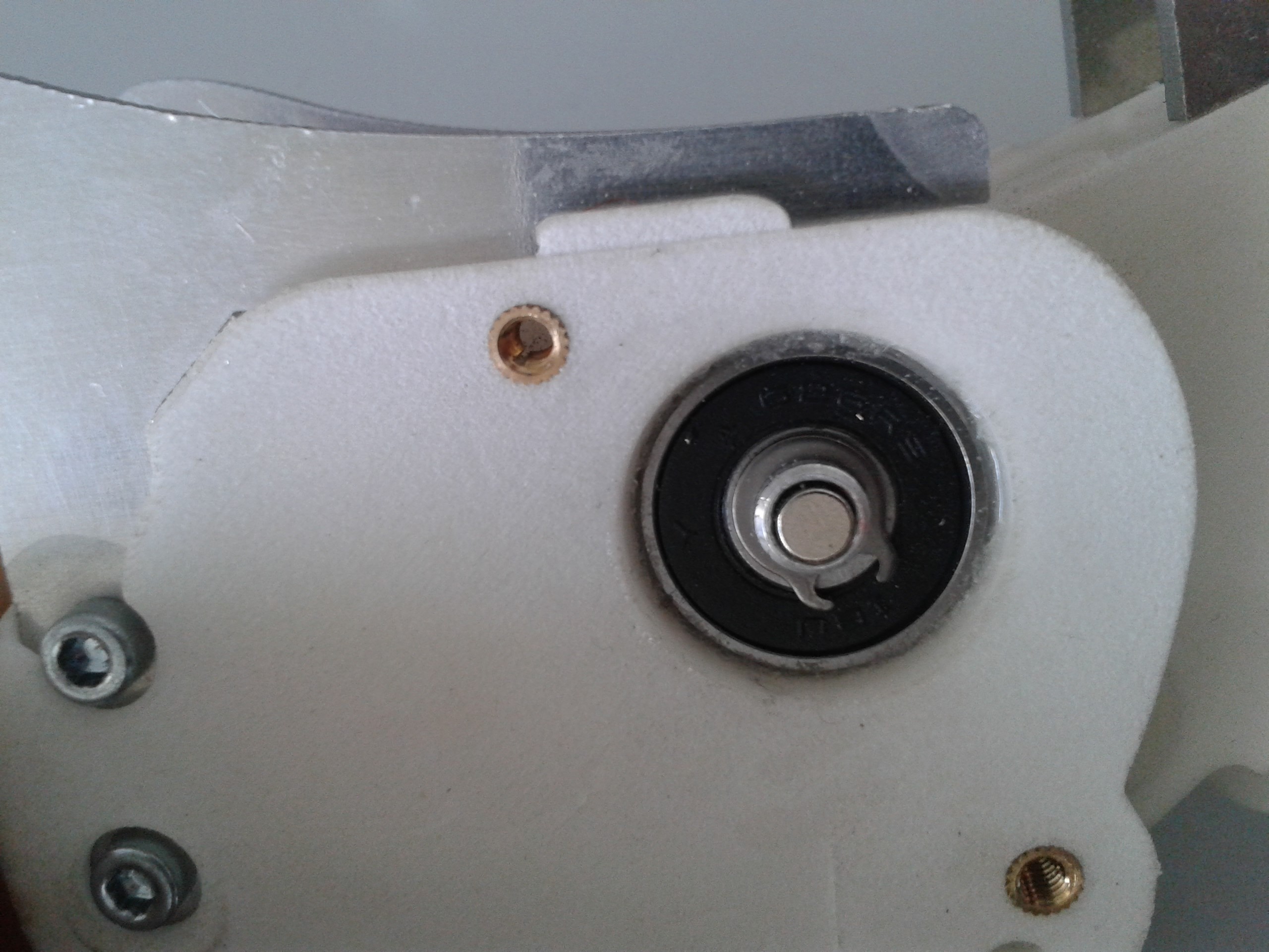
Fig. 3.33 Mount the other ball bearing. Mount the other small circlip. Glue the sensor magnet (use only a small drop of glue!). Note: the magnet can also be glued before mounting the joint axle.
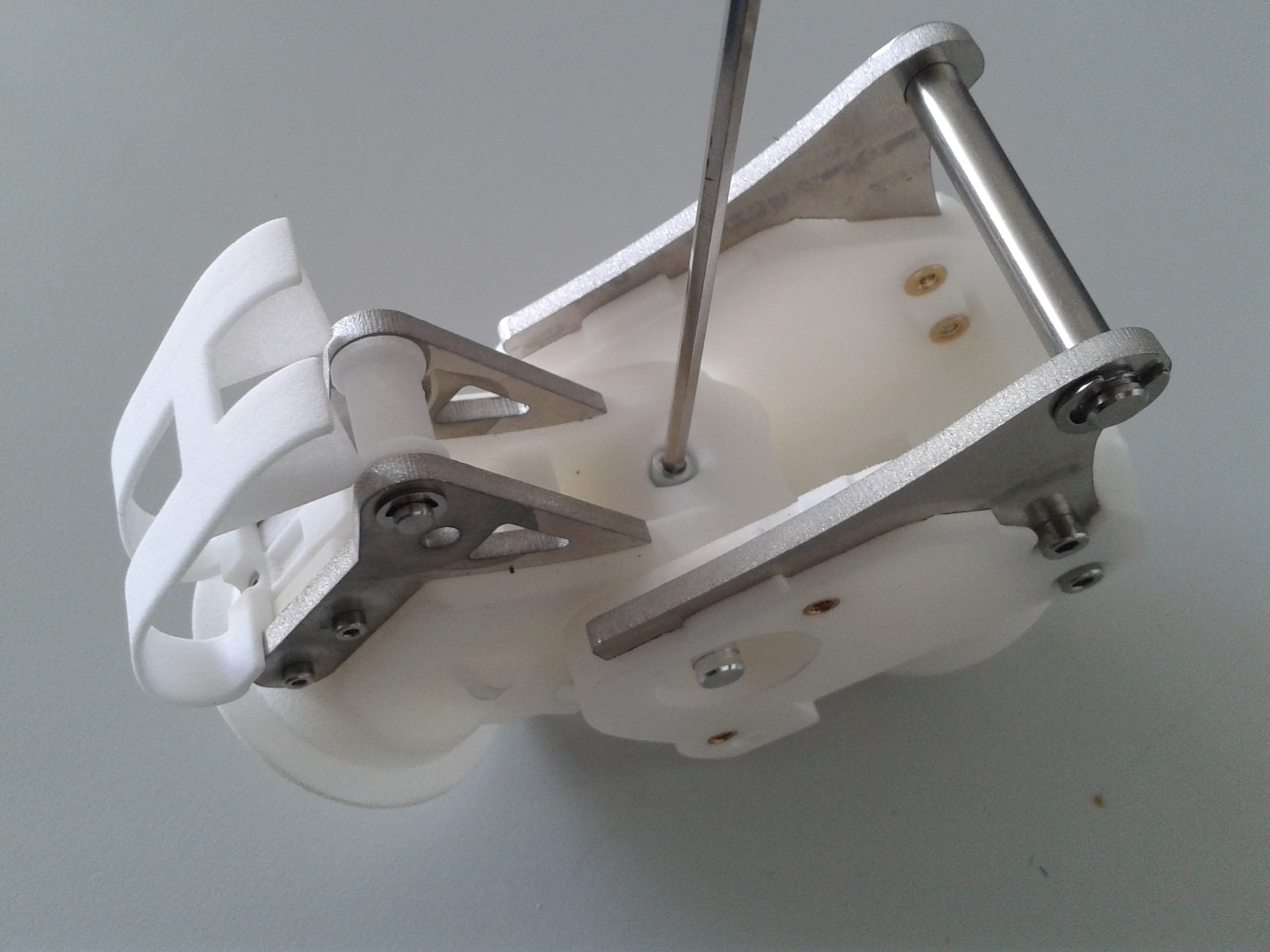
Fig. 3.34 Optionally: Secure the joint axle with the countersunk M3 screw.
3.1.3.6. Step 9: Mount the side covers
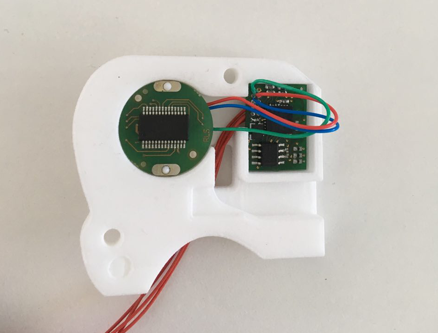
Assemble the sensor and SIM boards and the circular space in the larger side cover (glue the boards to the cover)
Check that the red, blue and green cables are facing upwards and the other red cables are behind
Screw the side covers on the under joint fork
3.1.3.7. Optional Step 10: Solder the cables on one of the SB connection boards
This step can be skipped if now SB connection boards are to be used.
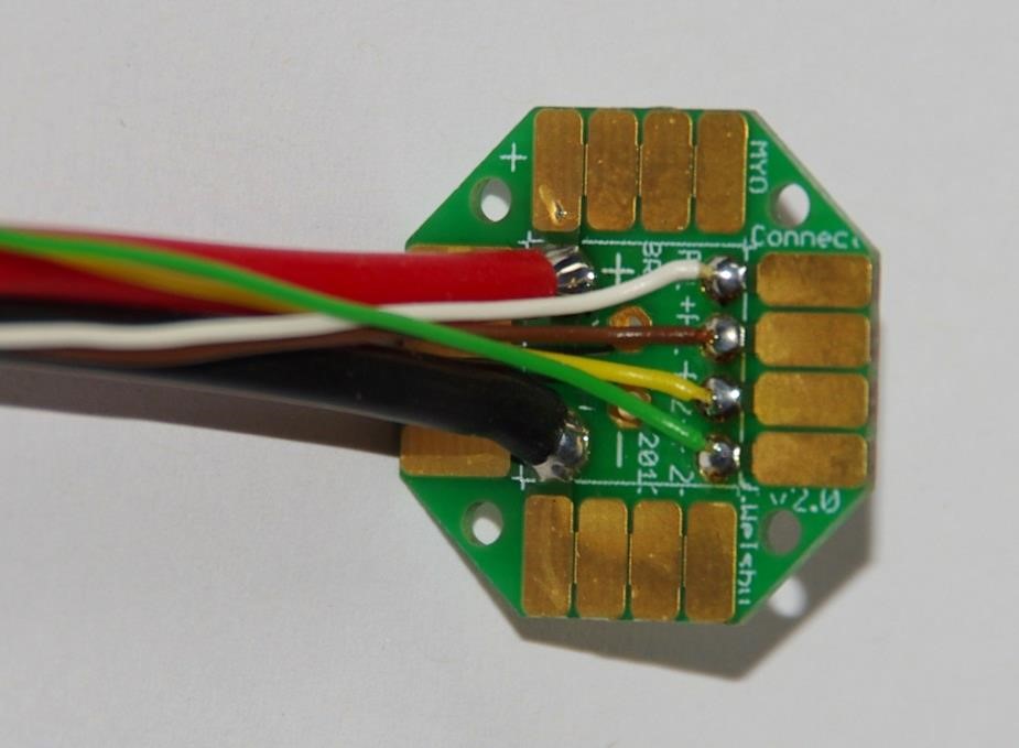
Prepare cable tree on connector boards.
Cut on 15 cm length:
4 data wires 0,25 mm2
2 power wires highly flexible silicon 1,5 mm2
Connector side:
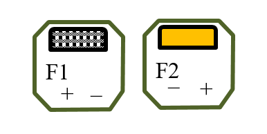
Pin colour code:
F1+ white
F1 - brown
F2 + yellow
F2 - green
3.1.3.8. Optional Step 11: Guide the cables through the joint and solder them to the other SB connection board
This step can be skipped if now SB connection boards are to be used.
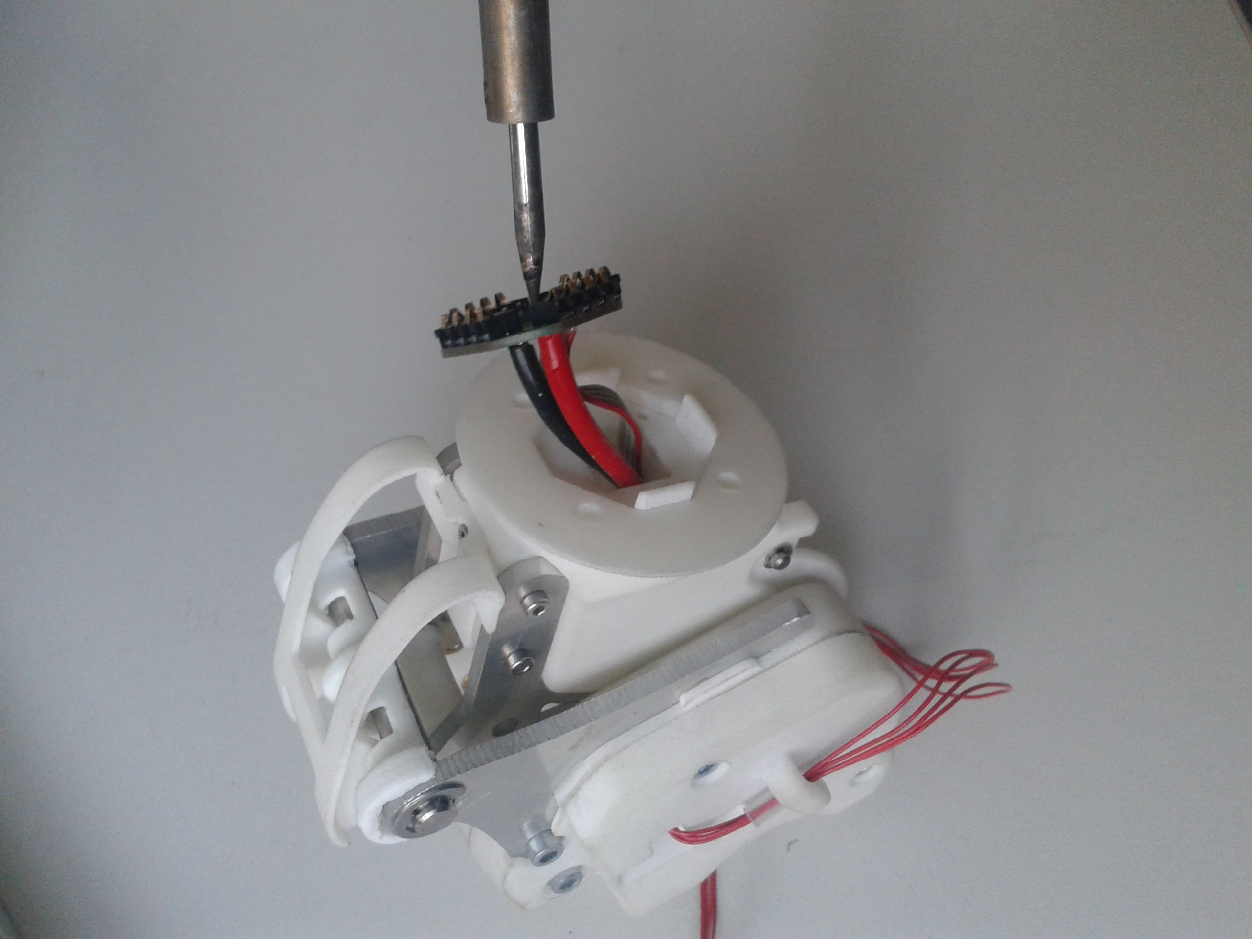
Strip all cables until the SB-pocket.
Pull cables through the connector board and solder from top. Screw both connector boards to joint with four M1,6 screws.
Connector side:
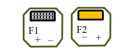
Pin colour code:
F1+ white
F1 - brown
F2 + yellow
F2 - green
Tips:
Put the joint in the position of the longest cable path!
Avoid cable crossovers by connecting to board