4.1. Muscle Mod Non-CE
These muscles are not CE conform due to the missing protecting bar covering the spring.
4.1.1. Parts List
The parts list is maintained at roboy.open-aligni.com.
External users can access it using the following credentials:
user: roboy
password: roboy
Level |
Manufacturer P/N |
Manufacturer Name |
Part Type |
Description |
Quantity |
Designator |
|---|---|---|---|---|---|---|
1 |
JFM-0304-03 |
Igus |
Bearings |
Igus Gleitlager JFM 0304-03 (Guide-Pulley) |
2 |
Cross-Guide |
1 |
JFM-0304-05 |
Igus |
Bearings |
Igus Gleitlager JFM 0304-05 (Guide-Roller) |
2 |
|
1 |
JFM-0608-06 |
Igus |
Bearings |
Igus Gleitlager JFM 0608-06 (Motor Reel) |
1 |
Tendon-Spooling |
1 |
MCM-12-02 |
Igus |
Bearings |
Igus Cliplager MCM-12-02 |
2 |
Displacement-Assembly |
1 |
2534-294 |
Wegertseder GmbH - Schrauben Shop |
Screws, Bolts and Rods |
Zylinderkopfschraube M 3x25 |
1 |
|
1 |
4001-205 |
Wegertseder GmbH - Schrauben Shop |
Screws, Bolts and Rods |
Selbstschneidende Schraube(Blechschraube) |
2 |
|
1 |
2534-236 |
Wegertseder GmbH - Schrauben Shop |
Screws, Bolts and Rods |
Zylinderkopfschraube M 2x8 |
2 |
Cross-Guide |
1 |
1160-043 |
Wegertseder GmbH - Schrauben Shop |
Screws, Bolts and Rods |
Senkkopfschraube M 2,5x10 |
3 |
|
1 |
1018-082 |
Wegertseder GmbH - Schrauben Shop |
Screws, Bolts and Rods |
Zylinderstift 3x24 |
1 |
Cross-Guide |
1 |
1018-076 |
Wegertseder GmbH - Schrauben Shop |
Screws, Bolts and Rods |
Zylinderstift 3x18 |
1 |
|
1 |
812 000 020.800 |
Kerb Konus |
Nuts, rings, inserts |
Brass Insert M2 |
2 |
Cross-Guide |
1 |
852 000 030.800 |
Kerb Konus |
Nuts, rings, inserts |
Brass Insert M3 |
3 |
|
1 |
M12 main body allConfig CE - new |
MyoRobotics Consortium |
MyoCAD |
body |
1 |
|
1 |
M11 main body cover |
Shapeways |
MyoCAD |
body cover |
1 |
|
1 |
M11 cable pulley horizontal |
Shapeways |
MyoCAD |
cable pulley |
1 |
|
1 |
M11 cross guide cover |
Shapeways |
MyoCAD |
cross guide cover |
1 |
Cross-Guide |
1 |
M11 cross guide roller - new |
Shapeways |
MyoCAD |
cross guide roller |
1 |
Cross-Guide |
1 |
D-311 |
Gutekunst Federn |
Springs |
Feder D-311 |
1 |
Displacement-Assembly |
1 |
myoMotorDriver |
Embedded Robotic Systems LLP |
Boards |
Motor Driver Board |
1 |
|
1 |
2534-288 |
Wegertseder GmbH - Schrauben Shop |
Screws, Bolts and Rods |
Zylinderkopfschraube M3x18 |
1 |
|
1 |
Spring Displacement Sensor Board |
Embedded Robotic Systems LLP |
Boards |
Sensor Board |
1 |
Displacement-Assembly |
1 |
MyoMuscle Assembly |
GI |
Labour |
0.75 |
||
1 |
Cable-Displacement-Sensor |
GI |
Tendon, Rope, Cables |
Displacement Sensor Cable |
1 |
Displacement-Assembly |
2 |
SHR-06V-S-B |
JST |
Tendon, Rope, Cables |
Connector Male - 1.0mm pitch/Disconnectable Crimp style connectors, with protrusions |
2 |
|
2 |
SH3-SH3-28150 |
JST |
Tendon, Rope, Cables |
Cable, crimped, 150mm for JST SH3 series |
6 |
|
2 |
MyoMuscle Assembly |
GI |
Labour |
0.25 |
||
1 |
458375 |
Maxon |
Motors |
Maxon Motor-Getriebe-Encoder-Kombination |
1 |
|
1 |
ISO 7379-4-M3-20 |
Ganter Griff |
Screws, Bolts and Rods |
ISO 7379 Passschrauben mit Bund Stahl, Festigkeit 12.9 |
2 |
|
1 |
Complete pulley spring displacement shaft without spring |
GI |
Machined parts |
Complete assembly of pulley, shaft, magnetic strip, threaded rod, but NO spring |
1 |
|
2 |
Assembly of pulley fork for displacement shaft |
GI |
Machined parts |
Pulley in fork to be installed on displacement shaft |
1 |
|
3 |
MyoMuscle Assembly |
GI |
Labour |
0.12 |
||
3 |
GN 751-4-8-M4-SL-AL |
Ganter Griff |
Screws, Bolts and Rods |
Gabelgelenke GN 751 aus Aluminium bestehen aus dem Gabelkopf DIN 71752 und einem Bolzen mit axialer KL- oder SL-Wellensicherung. |
1 |
|
3 |
SZU4-13 U604ZZ |
YongTian bearing Co.,Ltd. ( NBZH Precision Bearings ) |
Bearings |
Roller Bearing U groove 604UU 4*13*4mm |
1 |
|
2 |
Displacement shaft |
GI |
Machined parts |
Shaft holding the magnetic strip of the displacement sensor |
1 |
|
2 |
2210-850 |
Wegertseder GmbH - Schrauben Shop |
Screws, Bolts and Rods |
M4 DIN 976 Gewindestangen |
12 |
Displacement-Assembly |
2 |
KBEE5-1.2KL50 |
Bogen Electronic |
Sensors |
Linear Magnetic Scale Incremental |
5 |
Displacement-Assembly, Displacement-Sensor |
2 |
M11 spacer sleeve |
Shapeways |
MyoCAD |
spacer sleeve |
1 |
|
2 |
MyoMuscle Assembly |
GI |
Labour |
0.5 |
Assemble parts |
|
2 |
2012-104 |
Wegertseder GmbH - Schrauben Shop |
Screws, Bolts and Rods |
DIN 315 Flügelmuttern kleine Flügelform |
1 |
Displacement-Assembly |
2 |
1544-020 |
Wegertseder GmbH - Schrauben Shop |
Screws, Bolts and Rods |
M4 4,3 x 20mm Kotflügelscheiben |
1 |
Displacement-Assembly |
2 |
2896-150 |
Wegertseder GmbH - Schrauben Shop |
Screws, Bolts and Rods |
M4 DIN 934 Sechskantmuttern |
1 |
|
2 |
1900-144 |
Wegertseder GmbH - Schrauben Shop |
Nuts, rings, inserts |
Fächerscheibe Az 4.3 (für M4) |
1 |
|
1 |
SZU4-13 U604ZZ |
YongTian bearing Co.,Ltd. ( NBZH Precision Bearings ) |
Bearings |
Roller Bearing U groove 604UU 4*13*4mm |
2 |
|
1 |
M11 motor reel |
GI |
Machined parts |
Cable Winch |
1 |
Tendon-Spooling |
1 |
M11 Spring Sensor Wedge |
GI |
MyoCAD |
Wedge for holding in the magnetic encoder of the displacement sensor |
1 |
Displacement-Assembly |
1 |
2118-924 |
Wegertseder GmbH - Schrauben Shop |
Screws, Bolts and Rods |
DIN 913 Gewindestifte mit Kegelkuppe, mit Innensechskant “Madenschraube” |
1 |
Tendon-Spooling |
1 |
1708-844 |
Wegertseder GmbH - Schrauben Shop |
Nuts, rings, inserts |
Federringe B2 (for M2) |
2 |
Cross-Guide |
1 |
1556-202 |
Wegertseder GmbH - Schrauben Shop |
Nuts, rings, inserts |
|
1 |
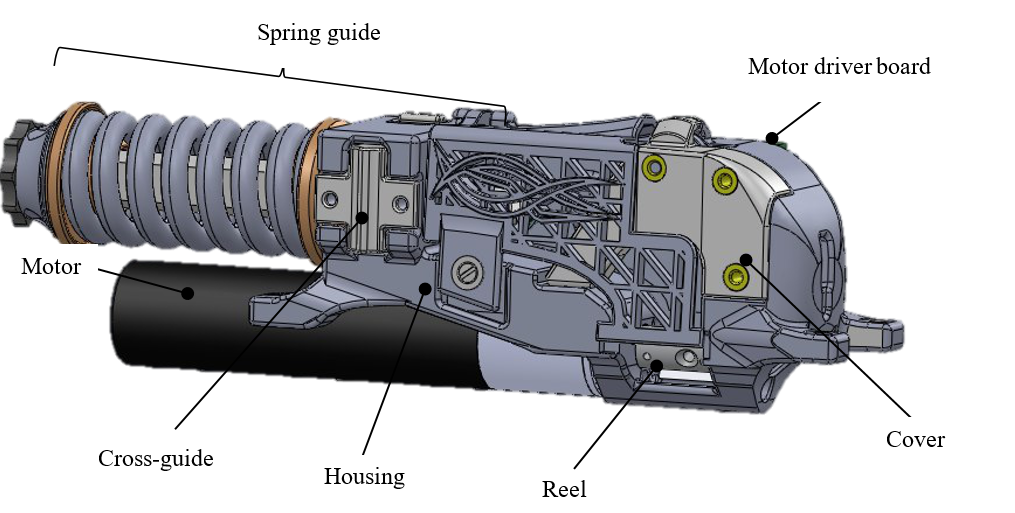
Fig. 4.3 Visualisation of a fully assembled muscle unit.
4.1.2. Step 1: Mount the plain bearings into the housing
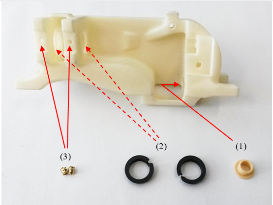
Fig. 4.4 Install the gliding bearings into the muscle housing.
Put the plain bearing (1) and the clip plain bearings (2) into the housing.
Put the two M2 inserts (3) in the holes of the housing.
4.1.3. Step 2: Assemble the pulley yoke and the spring guide shaft
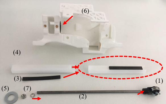
Fig. 4.5 Assemble the pulley yoke and displacement or spring guide shaft
Put screw glue into the screw thread of the pulley yoke (1) and connect it with the threaded rod (2).
Stick the magnetic strip (3) in the longitudinal groove in the spring guide shaft (4). The magnetic strip should be as near as possible to the pulley yoke as you can see in the example.
Slide the washer (5) down the threaded rod to the pulley yoke.
Slide the pulley yoke with the threaded rod from the right through the clip plain bearings (6) and put it in position.
Slide the spring guide shaft from the left through the clip plain bearings so that the threaded rod passes in its middle. Fix the rod on the shaft with the nut and washer (7).
4.1.4. Step 3: Mount the spring
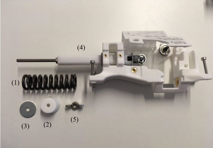
Fig. 4.6 Mount the spring.
Slide first the spring (1) then the spacer sleeve (2) from the left over the spring guide shaft (4) axle.
Use the washer (3) to push the spacer sleeve until it starts to preload the spring.
Then fix in place with the wing nut (5).
4.1.5. Step 4: Assemble the cross-guide
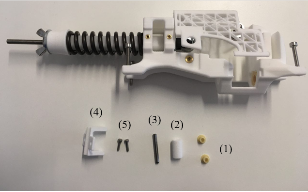
Fig. 4.7 Assemble the cross guide of the displacement shaft.
Insert the plain bearings (1) into the guide-roller (2) and insert the cylindrical pin (3).
Insert this assembly into the cross-guide (4).
Mount the cross-guide (4) into the housing.
Then screw in the two screws (5) to hold it in place.
4.1.6. Step 5: Assemble the cover
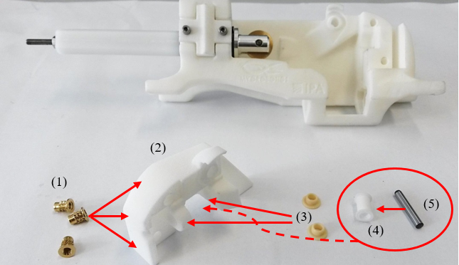
Fig. 4.8 Assemble the muscle cover and tendon guide.
Press the three M3 inserts (1) into the cover (2).
Insert the plain bearings (3) in the cover and place the printed pulley (4) between the plain bearings.
Fix the printed pulley to the cover by inserting the cylindrical pin (5) through both the pulley and the plain bearing. The pin must be pressed in the pulley.
4.1.7. Step 6: Mount the cover and the pulleys on the housing
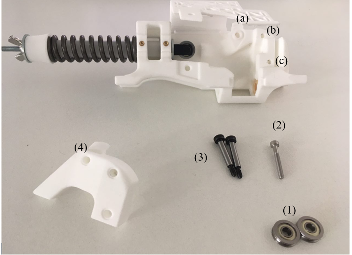
Fig. 4.9 Placement of guiding pulleys in muscle housing.
Insert the screws (2) and (3) from the back of the housing in holes (a), (b) and (c). One black screw (3) must be in hole (a).
The other black screw (3) goes in hole (c) as an axle for one of the bearings (1) and other black screw in hole (a) acts as another axle for the other bearing (1).
Mount the cover (4) on the housing and tighten all screws. Make sure that the brass pulley can still rotate freely.
4.1.8. Step 7: Mount the reel on the motor shaft
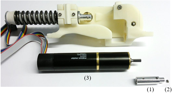
Fig. 4.10 Fixing tendon reel on motor shaft.
Put screw glue on the setscrew (2).
Mount the reel (1) using the setscrew on the shaft of the motor (3).
4.1.9. Step 8: Mount the motor and the motor driver board
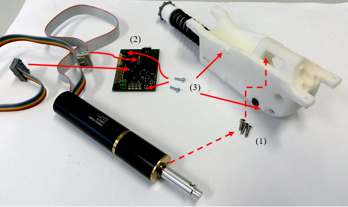
Fig. 4.11 Mounting motor and driver board to muscle housing
Use the three screws (1) to mount the motor to the housing.
Connect the motor to the motor driver board (2).
Mount the board with the screws (3) to the housing.
4.1.10. Step 9: Connect to the dispacement sensor to the Motor board
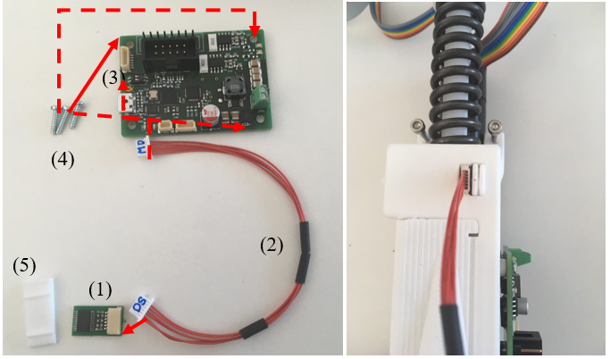
Fig. 4.12 Mounting of the displacement sensor on the muscle unit and cabling to the motor driver board.
The motor board (3) should already be attached by the screws in previous step.
Insert the DS header (displacement sensor pins) on wire (2) into the displacement sensor (1).
Then the MD header (motor driver board pins) on wire (2) into the motor board.
Then place the displacement sensor (1) into the slot on top of the housing unit and secure it using the wedge (4) as shown in the photo on the right.
The side of the displacement sensor shown Fig. 4.12 should be on the inside of the muscle houseing, close to the magnetic strip on the displacement shaft.